Jonathan,
You are correct about cascodeing current sources I have found that this is one method to get the most of the current source.
With regard to the current source on the second differential would you not have to set it to twice the value compared to just using a current mirror only ?
Jam
You are correct about cascodeing current sources I have found that this is one method to get the most of the current source.
With regard to the current source on the second differential would you not have to set it to twice the value compared to just using a current mirror only ?
Jam
Jam:
For the second stage in a dual-differential stage, the summing current-mirror is (almost always) operating at a 1:1 ratio (no gain), and can tolerate a wide range of currents without much difference in performance. I usually determine the currents that I will use on the basis of the differential devices' maximum ft (rather than noise), or whatever level of current is required to fully drive the succeeding stage (whichever is greater). If you calculate like this, I do not think that the amount of current desired will change, whether the loading (and/or summing) of the differential stage is accomplished by resistors, single active devices or a current mirror.
regards, jonathan carr
Theory is one thing - Circuits another
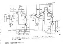
We have seen a practica example of a differential
in a schematic by Kaneda. See above!
Now there is a discussion about two different ways to design.
I want to see a good example
of this folded cascoded.
Elso and other posters have a liking of this type
of amplifiers.
Would be interesting to see a schematic.
Makes me and other fellows here
be more interested in your discussion.
We also want to know more!
And feel being a part of your theoretical discussion.
Regards to you all
halo
----------------------------
Schematic shows a differential input with bias set by resistors:
Kaneda preamp:
Attachments
Jonathan,
Thanks for your reply, you certainly have helped improve my understanding of the dual differential topology. As Holojoy has put it, maybe you could give us a circuit (line amp) to analyze and build, maybe even start a new thread on. This seems to be one topology worth investigating further.
Thanks again.
Jam
SUN UP
Hi,
The "Le Solstice" preamp surely was a standard setter back then.
I'm a tube fellow and I admit I had a lot of respect for this one although to my ears all Hiraga's tube designs beat it hands down on colours, dynamics and sheer musicality.
Not that those designs were perfect in any way...
The Kaneda,at least to the original specs is virtually impossible to build nowadays,not to mention the fact that almost all designs published in "L'Audiophile" contain deliberate mistakes.
Caveat emptor,")
Hi,
The "Le Solstice" preamp surely was a standard setter back then.
I'm a tube fellow and I admit I had a lot of respect for this one although to my ears all Hiraga's tube designs beat it hands down on colours, dynamics and sheer musicality.
Not that those designs were perfect in any way...
The Kaneda,at least to the original specs is virtually impossible to build nowadays,not to mention the fact that almost all designs published in "L'Audiophile" contain deliberate mistakes.
Caveat emptor,
SUN DOWN.
Hi Jam,
I doubt it...
Jam,I'll look through my issues but I honestly doubt I have anything workable for you in my "L'Audiophile" issues.
This was a commercial design based on the Kaneda work with a lot of of attention to detail such as passive components.
You may be able to find a second hand unit though and if you need some English to French or vice versa translations I'll be happy to help.
Cheers,
Kaneda ... folded cascodes ... 2SK30
If I recall correctly, the first commercial Kaneda, the DC1, had 2SK243 (a double 2SK43) in the first stage, and the later Solstice had 2SK240. These informations are in the numerous articles in the French L'Audiophile magazin. The 2SK30 is available without problems, at 50c each, but there are two versions, one in the normal TO92 case, and another, slightly different, in a more rounded case, with magnetic leads, which sounds less good. The Y selection has better Idss stability than GR, so I did choose Y for selection. Operating point is about 250uAmps anyway.
When I changed from the baisc DIY-Kaneda (2SK30 really sounds best there) to folded cascode, I needed a darlington output stage, because I lost some gain, and it wasn't enough for my active RIAA any more. I used 2SK97 (you can see it as a monolithic 2SK43) in the input. What I got was very good and detailed treble and midrange, but I lost in bass. This might be partly due to the active RIAA, but I also had the impression, that the thermal distortion of the second stage was mirrored by the input stage. I used resistors for biasing the emitter currents of the second stage,
thus a Vbe variation in the cascoding transistors translates in changing biasing currents - maybe with current sources this improves.
Anyway I got the impression that this kind of circuit needed more complexity to work satisfactorily and went back to double differentials.
Today I am using a simple double differential with current mirror and a complementary output, but I am using low impedances all through the circuit and a lot of local feedback resp. degeneration, too. I am working with bipolars only, no Jfets any more. There is no Jfet that I would like to listen music through longer than one or two hours. Most Jfets make the music sound like plastic, the best types sound a bit like tubes.
I intend to change my pre to passive RIAA and two gain stages. I found it extremely difficult to tune the stages of the RIAA circuit to have good treble as well as good bass performance.
I also tried a later Kaneda preamp, published 1995 in MJ, and found that it had way better resolution and soundstaging and all that, but lost some of the tube magic that the old circuit had.
regards,
Hartmut from Munich
Leach preamp
Maybe because it is also old. 1977...
But then old designs can be VERY GOOD in some aspects.
###############
W.Marshall Leach - Links to his Ampdesigns/Papers
Leach - Wide Bandwith Preamplifier - Article PDF
###############
I did a CUT-OUT of the MAIN SCHEMATIC of this Preamp
It is also in my music & schematics website
/halo - web audio research
Yes, sdman, it looks same.sdman said:Has anyone built the Wide Bandwith Preamp by Marshall Leach?
It looks similar to the Kaneda, but with a different output.
Sam
Maybe because it is also old. 1977...
But then old designs can be VERY GOOD in some aspects.
###############
W.Marshall Leach - Links to his Ampdesigns/Papers
Leach - Wide Bandwith Preamplifier - Article PDF
###############
I did a CUT-OUT of the MAIN SCHEMATIC of this Preamp
It is also in my music & schematics website
/halo - web audio research
Attachments
I frequently see folded-cascode circuits that use resistors as current sources, but in my opinion and experience, this is not a wise idea. The better the current source is, the better the folded cascode circuit will work and sound. I use cascoded current sources for my folded cascode circuits, and I accomplish all of the biasing via voltage regulators. If you want good bass, current sources that absolutely don't waver and ultra-stiff biasing schemes will both pay handsome dividends.
Although a folded cascode may require additional support circuitry, and may therefore _look_ more complex than dual differentials, the signal path is actually simpler and cleaner than dual differentials, and a folded cascode is easier and more straightforward to stabilize.
To quickly describe some of the advantages of folded cascodes over dual differentials, let me quote from the Analog Devices AD-797 data sheet, page 9. "The AD797, due to its single-stage design, has the property that its noise is flat over frequencies from less than 10Hz to beyond 1MHz. This is not true of most DC precision amplifiers where second-stage noise contributes to input-referred noise beyond the audio frequency range. In sample data systems, where aliasing of out-of-band noise into the signal band is a problem, the AD797 will out-perform all previously available IC opamps."
Now, as to whether we should rank a particular device or class of devices according to personal preference, my advice is rather than painting yourself into a corner, to use whatever devices are best suited for the application. And the better you are at analyzing and comprehending the circuit that you have, the better your chances will be to locate the optimal devices.
I do not deny that subjective aspects like musicality, tonal complexity and "magic" are nice to have, but it is surprising (perhaps shocking is a better word) how much these qualities are tied to mundane, unromantic issues like how the wiring networks are designed and routed, or how the circuit is constructed (including the circuit-board layout). If the circuit topology and circuit construction issues are all up to snuff, it is entirely possible to make a magical-sounding component using completely normal components that many audiophiles would treat with disdain.
hth, jonathan carr
Current Sources?
Hi Jonathan,
Thanks for elaborating but were are the current sources implemented ?(for the long tailed pair, the curent mirror load of the folded cascode or....?)
It might be helpfull to include a simplified schematic of your ideas. I find this thread hard to follow.
Hi Jonathan,
Thanks for elaborating but were are the current sources implemented ?(for the long tailed pair, the curent mirror load of the folded cascode or....?)
It might be helpfull to include a simplified schematic of your ideas. I find this thread hard to follow.
Dear Elso:
For this discussion, let us assume that we are talking about an N-input differential combined with a P-folded-cascode.
IMO, regardless of whether the overall topology is dual-differential, complementary differential or folded cascode, the long-tailed input pair of _any_ differential must sit on a constant current sink for proper differential operation. Fixed-cascode current sinks are a good method for this task, because they insure that the current value remains truly constant regardless of operating conditions, and they can have very high output impedance. Another valid option would be a current-source feeding the input of a current-mirror, with the output side of the current mirror acting as the current sink. Because the input side of the current mirror wouldn't be connected to anything relating to the signal, this would prevent the current from being modulated as the input pair swung according to the signal. But OTOH, the output impedance from a current mirror isn't as high as you can get from a good fixed cascode. So on the whole, my vote would be for my original suggestion of a current-sink feeding a fixed cascode.
Moving on to a folded cascode, one way of analyzing such a circuit is to consider it as a master current source (let's call this Itotal) feeding two current sinks - the input differential (let's call this Ia), and the folded-cascode section (let's call this Ib). From the resulting equation, Itotal=Ia+Ib, we can see that as long as we insure that any two of the current elements are fixed and constant, the third current element will be fixed and constant, too.
Although on paper it is possible to make all three current elements constant-current, in practice there will be some difficulty in matching the current values so that Ia+Ib actually do equal Itotal. I tried this once, using individual current elements, and the result was a bunch of split transistors and a burnt circuit. _If_ I were to attempt this again (for example, to test out the bootstrapped summing current mirror used in the Analog Devices AD797), I would arrange everything as a single master current source supplying an array of current mirrors.
If you would like different, in-depth analysis of the folded cascode, please look at this patent by one of my design heros, Masao Noro:
http://patft.uspto.gov/netacgi/nph-...,406,990.WKU.&OS=PN/4,406,990&RS=PN/4,406,990
hth, jonathan carr
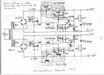
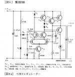
Frank,
I think there is an error in the drawing.
I believe the base of the 2SC1777 and 2SA872 should be tied to the positive and negative rails through a resistor respectively for the regulator to work. This forms a voltage divider for the above transistors to work. The schematic shows the bases tied directly to the output rails.
Jam
KANEDA MOD.
Hi Jam,
That's quite possible,I really can't help you here.
I'm rather ignorant as far as solid state designs go.
If I can trace back the circuit source I'll be glad to inform you.
Can't remember where I got this from.
Cheers,
Hi Jam,
I think there is an error in the drawing.
That's quite possible,I really can't help you here.
I'm rather ignorant as far as solid state designs go.
If I can trace back the circuit source I'll be glad to inform you.
Can't remember where I got this from.
Cheers,
jam said:
I think there is an error in the drawing.
Jam,
the gate of the negative rail current source JFET is tied to the drain and not the source.
Fdegrove,
Thanks for reposting my schematic of Kaneda power amp regulated power supply.
http://www.diyaudio.com/forums/showthread.php?postid=55559&highlight=Kaneda+power+supply#post55559
regards,
Hartmut
- Status
- This old topic is closed. If you want to reopen this topic, contact a moderator using the "Report Post" button.
- Home
- Source & Line
- Analog Line Level
- kaneda preamp