No George, 47R it is.....
BTW, for winding the inductor, just choose a medium size philips head screwdriver. They make an EXCELLENT former, one you can remove, and leave behind a perfectly formed coil for mounting on the board.
Just remember, when winding, hold screwdriver handle in right hand, wire with left, secure the wire end 1" on the body of the screwdriver with right thumb, then start winding towards you from the top, and down, under, back up on other side, that is, CW viewed from the left hand end.
Always keep the wire hand (left) slightly to the right of the coils as you wind, so they pack closely. Otherwise, there will be large gaps between turns, which looks very untidy.
Hugh
Last edited:
I temporarily want to run my boards with 18VAC transformers , until I get some new transformers. In the construction guide it says to adjust "the voltage across the bootstrap resistor R12 to 24-26 volts (P3)". What should this be set to if I'm running at this lower voltage? (assuming it is OK to do so!)
col_s,
Adjust R12 so that the minimum voltage across the dn2530 current source is about 3 volts (Drain to Source voltage). This will keep the dn2530 acting as a current source, and minimize the dissipation in it.
18 Vac transformer should give you 22 volt rails. Setting R12 to 1K (from 2.2k) should give a minimum of 3 volts (when the rail sags a bit) and a dissipation of less than 100mW.
Paul Bysouth
Here is my finished version of Fetzilla amp. I was playing music for the last two days and I am really impressed by quality of sound. Bass and vocals are excellent. Piano sound is as close to real thing as you can get in both classical and jazz music. Also guitar sound is very detailed and real without any coloration. Sorry guys for not using any poetic language for sound description but I will leave that for others who didn't built it yet. It is a keeper for me, thank you to all contributors to this project.
George
George
Attachments
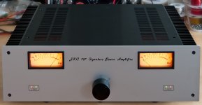
George,
Beautiful work, very elegant, like the VUs a lot!
But, I note it is a JKC 787 (is that a Dreamliner?) case, not a FetZilla!!
I enjoyed your description of the sound, you will make an audio novelist yet!
I live in hope that others, as they complete their FetZillas, will post their impressions - good and bad, let's keep it credible - on this thread. It is fitting closure and appropriate feedback for what has been a very successful design, and indeed, Group Buy.
Cheers,
Hugh
Woody,
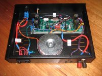
Actually, my build is anything but stock. The major difference from original design is stand alone power supply with bigger transformers and bigger filtering caps. Because of that I used only 3300uF on the board itself to make it even faster in big current swings. I also used two additional circuit boards, one for soft start and another for VU meters. Another change I have made is zobel network at the output. I used pi filter there with those values: 47nF/8.2ohm, 2uH with 2ohm in parallel, 68nF/5.1ohm (this leg mounted on output terminals). That is all. Currently I am running this amp with VAS at 13mA and bias 450mA settings. Have fun.
Hugh,
Thanks. It is just name and has nothing to do with the planes . I have Fetzilla name on the back plate however, so nothing is lost.
George
At last I have finished my pair of FETzilla monobloc amps. I have used Hugh's NAKSA-70 chassis, in which the FETzilla fits very nicely. The chassis is one piece of folded 3mm aluminium, and acts as the heatsink. At a bias of 390mA, I can only just feel some warmth under the mosfets.
I too am very impressed by the sound.
Paul Bysouth
Lovely work, Paul, very neat and tidy. Congratulations! HRD
I too am very impressed by the sound.
Paul Bysouth
Lovely work, Paul, very neat and tidy. Congratulations! HRD
Attachments
Last edited by a moderator:
hey guys , a few questions ...
1. is there a reason that Rz needs to be inside of the inductor instead of just mounting on the underside of the board where we've already got the mosfets and power supply cap resistors ?
2. what is the final determination on silver mica's c5 & c6 . i recall Hugh saying they were needed , but was that just for difficult speaker applications or needed in all situations ? i notice that JKC didn't use them .
3. in adjusting P1 , where are you measuring bias current ?
i really appreciate all your newbie friendly advice and help")
cheers Woody
1. is there a reason that Rz needs to be inside of the inductor instead of just mounting on the underside of the board where we've already got the mosfets and power supply cap resistors ?
2. what is the final determination on silver mica's c5 & c6 . i recall Hugh saying they were needed , but was that just for difficult speaker applications or needed in all situations ? i notice that JKC didn't use them .
3. in adjusting P1 , where are you measuring bias current ?
i really appreciate all your newbie friendly advice and help
cheers Woody
- Status
- This old topic is closed. If you want to reopen this topic, contact a moderator using the "Report Post" button.
- Home
- More Vendors...
- AKSA
- Swordfishy/ASPEN FETZILLA power amp