Emitter resistors ensure proper current sharing though introducing local negative feedback, In our headphone aplication I will not add polyfuses in the sound path although I have done so on occassion. They are in fact positive temperature coefficient resistors that has a low cold resistance say 5 ohm while when the fuse introduce a high resistance say 10kOhm. Once they recover and the fault removed they return to the cold resistance.
I was talking about the polyfuses that Nico mentions using in an amp successfully.
That's not how I learn.
If I don't understand a particular part of the amp, I leave it out of the schematic and then post it online... In at most 2 days I am educated on the matter.")
That's how I learned about emitter resistors, anyway.
- keantoken
it's a good thing to look at the different elements of the amp and ask 'why'.
That's not how I learn.
If I don't understand a particular part of the amp, I leave it out of the schematic and then post it online... In at most 2 days I am educated on the matter.
That's how I learned about emitter resistors, anyway.
- keantoken
KT, Gareth,
Emitter resistors are the means whereby we stabilise the bias setting, and in a multiple output pair amp, ensure current sharing, which is compromised by varying Vbe between unmatched devices.
Let's give an example. Quiescent of 100mA, emitter resistor of 0.22R, typical values. We have 22mV of voltage dropped across this resistor at bias, and with around 600mV dropped across Vbe of the output device, it's easy to see that this 22mV is more than an order of magnitude lower, in fact, it is only around 3.7% of the voltage dropped across the transistor base/emitter junction. Put another way, if one transistor had a Vbe of 590mV, and another 600mV, then clearly more current would flow through the 590mV transistor. Our emitter resistor would indeed pass more current, but then more voltage would be dropped across it, say 28mV, giving a quiescent in this device of 127mA, but in fact at this higher current, the Vbe of that transistor would also increase to around 594mV simply because it IS passing more current.
If we increase the emitter resistor to 0.47R, keeping our quiescent at 100mA, the voltage dropped across it is now 47mV. We increase the bias voltage slightly to keep it at 100mA in our reference output device, and note the changes in our mismatched device, whose Vbe is now at 593mV. However, that means that its emitter resistor is dropping 47mV + 7mV, or 54mV, which means the mismatched transistor is now passing just 115mA - a big improvement over 127mA in the earlier example and far closer to the under-run device coasting along at 100mA.
Clearly a larger emitter resistor forces superior current sharing, but at the expense of output impedance, as you say.
But it's not as bad as you think.
Firstly, we are driving cans, which drop to 24R, a much easier load to drive than 8R speakers. Secondly, the output impedance of a feedback amp is ameliorated by global feedback, and in fact reduced from local, single stage considerations by the loop gain (close approximation), which in this case is 39.3dB at 1KHz, representing a factor of 92.2 Our Zout is the addition of re to the emitter resistor, which is (26/40 + 10) at quiescent levels of stage current, giving 10.65R. Divided by the loop gain of 92.2 at 1KHz, we have an effective Zout of just 0.115R, which with cans of just 24R gives a damping factor of 208. This is so high that even with a series resistor (120R as specified by the IEC standard) it is academic, of no real significance to sound quality.
Cheers,
Hugh
Last edited:
Member
Joined 2009
Paid Member
Member
Joined 2009
Paid Member
How are we doing with the overall schematic now ?
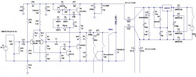
I've attached a kind of summary - probably has several errors but perhaps now's a good time to start pulling together a 'reference' plan. KT has most of this in sims already which might be a better starting point - I don't even have the regulator placed properly !
What I have contains:
Hugh's masterful amplifier & PSU
triple diode bias string, aimed at 40mA
increased output cap
volume control
Input decoupling
Glen's checks on OLG/CLG/Stability
AndyC's tips on simulations
MJL21193 & OS input on tons of stuff
KT's bootstrap and insights and doing a lot of the 'heavy lifting'
Ikoflexer's persistance that resulted in a proper regulator
Nico's CF and words of wisdom
Paul's Mute option
Sandy's output resistor
We will include Line-Out ?
We will include dc-power in for external supply option
....and many other contributions (Sheldon) that I can't keep up with it all
Are there still questions about these items, did I miss something or somebody ?
Was there consensus on the subject of tone controls or a tilt function - Gaetan ?
Attachments
Member
Joined 2009
Paid Member
What is the purpose of mute if R21 is present? I was under the impression that mute was for headphone protection during cap charge-up.
Gareth, which coils are you using, where can I see a footprint.
Furthermore I see a number of ground signals, where is ground? It is tied through 10 ohm to negative, why?
Nico
Gareth, which coils are you using, where can I see a footprint.
Furthermore I see a number of ground signals, where is ground? It is tied through 10 ohm to negative, why?
Nico
Member
Joined 2009
Paid Member
What is the purpose of mute if R21 is present? I was under the impression that mute was for headphone protection during cap charge-up.
Gareth, which coils are you using, where can I see a footprint.
Furthermore I see a number of ground signals, where is ground? It is floating somewhere in space.
Nico
I'm half-expecting some further discussion on R21 as to whether it should be smaller, adjustable or swithable, but you are right, if we leave it as is we might be able to simplify further.
Coils - I haven't looked at all the suggestions yet, sorry no footprint

Ground - This needs some discussion to avoid 'hum' etc. I had envisaged both channels floating above the chasis, the 'lower rail' connected to the chasis through a bridge rectifier, which further separates the channels from each other. I saw this somewhere on one of Nelson's designs - should I draw a diagram ?
Member
Joined 2009
Paid Member
If you tie the capacitors all through 10 ohm to ground then you forcing the caps to have ESR = 10 ohms, this is not good.
I don't think I've understood my error yet ? - I'm looking at caps as being between rails or between 'a' and 'b'. I don't worry about where ground is at all, I only look where currents flow. The idea is, I can put ground anywhere on the circuit - it's just a point of reference ?
Hi Gareth, because of the single supply, the "ground" is effectively the negative supply. Now looking at C11, C13 they are tied through R19 forcing their ESR=10 ohms.
Also have a look at the signal current, if the signal swings negative (in other words Q4 turns on) how does the current flow?
Don't get me wrong, I am not directing these questions at you personally Gareth it is to anyone out there.
Nico
Also have a look at the signal current, if the signal swings negative (in other words Q4 turns on) how does the current flow?
Don't get me wrong, I am not directing these questions at you personally Gareth it is to anyone out there.
Nico
One final question. This is regarding the headphone impedance, I know of some having a low impedance around 32 ohms, most decent headphones have a much higher impedance around 200 - 500 ohms, why did we select 23 Ohms and why a 1000 uF pass capacitor, anyone though about that? As it stands the frequency is 7Hz, anybody listen to this?
What is the purpose of a zobel network and for what load is it designed or is its purpose just to shunt some oscillation and at what frequency seeing that we have headphones varying in impedance from 23 ohms to 500 ohms. Nobody questions these things and take it for granted.
I believe one of Hugh's objectives are for you guys to learn something as well as come up with the final design collectively. Some have added good ideas others seem to accept their fate like an animal led to slaughter.
Ask questions someone will respond and everyone will benefit greatly. Besides you will be proud to have a part in this when it is complete.
Kind regards
Nico
Ask questions someone will respond and everyone will benefit greatly. Besides you will be proud to have a part in this when it is complete.
Kind regards
Nico
Member
Joined 2009
Paid Member
Hi Gareth, because of the single supply, the "ground" is effectively the negative supply. Now looking at C11, C13 they are tied through R19 forcing their ESR=10 ohms.
Also have a look at the signal current, if the signal swings negative (in other words Q4 turns on) how does the current flow?
Don't get me wrong, I am not directing these questions at you personally Gareth it is to anyone out there.
Nico
Ask away, I'm not a shy person
OK, here's how I see it. C11 and C13 are there to decouple the 'upper rail' with respect to the lower rail and NOT with respect to the chasis. So R19 is no hindrance ?
Ask away, I'm not a shy person
OK, here's how I see it. C11 and C13 are there to decouple the 'upper rail' with respect to the lower rail and NOT with respect to the chasis. So R19 is no hindrance ?
But that's not what you have drawn. C11 and C13 are shown as connected to "earth" and R19 connects the negative rail to earth. If you connect C11,13 to the negative rail instead, then R19 is not in series with the caps.
Do you need an earth connection with a 25V rail? It's already isolated in the power supply. Also, if a wall wart is used, it won't be earthed anyway.
Sheldon
Last edited:
Member
Joined 2009
Paid Member
Yes - you're right. I said the right thing but didn't draw it that way.
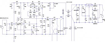
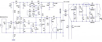
Here's an updated drawing - I've remove the mute switch - we'll put it back if the 120R resistor is questioned and removed before we finalize.
Note that the "Rcorssfeed" is supposed to represent a potentiometer for user adjustment.
Here's an updated drawing - I've remove the mute switch - we'll put it back if the 120R resistor is questioned and removed before we finalize.
Note that the "Rcorssfeed" is supposed to represent a potentiometer for user adjustment.
Attachments
Last edited:
- Home
- More Vendors...
- AKSA
- Aspen Headphone Amp