Member
Joined 2009
Paid Member
What movie?")
Duplicity, staring Julia Roberts - I'm a fan.
It's not an easy movie to follow, but very enjoyable.
I hooked up my DIY sub-woofer to the TV for the first time - nice addition !
Member
Joined 2009
Paid Member
It doesn't seem like hum is a problem in Hugh's other amplifiers, which are not headphone amps. So it should be possible to get satisfactory performance without the regulator. So I could go either way.
There is one thing I want to make note of. A Jfet current source has somewhat poor PSRR, but it adds plenty of H2. Recall the input bias configuration I used. It actually increases H2 in the simulator. Should we try it?
- keantoken
I have played with some simulations (my Harry 77 thread) using a JFET in various locations to purposely increase H2 and/or to emulate triode-like distortion effects. It's a nice method and the JFET is a very interesting device, having a different characteristic than all other active devices. My favourite trick in the Harry 77 amp was putting the JFET into the nfb loop.
What I found in the sims was that adding H2 in a multi-stage NFB amp is quite difficult - because it invariably results in increased risk of IM distortion at higher signal levels. I did some real DIY experiments with my TGM1 amplifier (another thread) although not with the use of a JFET for this. The higher H2 gives a nice sound, but when I crank up the volume it gets muddy pretty quickly.
It would be risky to include it in this headphone amp without prior experiments simply because it's a one-shot chance at the pcb. If Hugh prefers to keep it clean all is not lost since you and I can butcher the pcb with fly-wires and try out something along the lines you have suggested
Duplicity, staring Julia Roberts - I'm a fan.
It's not an easy movie to follow, but very enjoyable.
I hooked up my DIY sub-woofer to the TV for the first time - nice addition !
Ah, I've been meaning to see it.
Good bass is the foundation to build on - it make everything sound better.
Member
Joined 2009
Paid Member
The Jfet is not at all in the feedback loop. I think it is perfectly safe here.
- keantoken
sorry, I didn't explain. I was saying that in general, I like JFETs and I like the application of them to controlling H2. And that I had tried it in a NFB loop, I realize you weren't suggesting that here.
I think your suggestion for the bootstrap take-off point is the better approach. It might be worth playing with the relative values of the bootstrap divider resistors to see if we have them optimized, I haven't looked at that at all yet.
Edit: here's a nice all-on-one pcb headamp to give us some ideas about construction...
http://4.bp.blogspot.com/_ZVgJtItVg..._WnQ/s1600-h/High-End-Headphone-Amplifier.jpg
Last edited:
Since the PS is not finalized, let me make a suggestion.
I designed and built a very smartly working phone stage

that is powered by a wall wart. The wall wart has ac output, and the benefits are that the PS itself is left in your hands - you can make it any way you want; also the transformer (and mains wiring) is not close to the amp circuit. One more plus: no bulky cord to the unit itself.
I designed and built a very smartly working phone stage
that is powered by a wall wart. The wall wart has ac output, and the benefits are that the PS itself is left in your hands - you can make it any way you want; also the transformer (and mains wiring) is not close to the amp circuit. One more plus: no bulky cord to the unit itself.
sorry, I didn't explain. I was saying that in general, I like JFETs and I like the application of them to controlling H2. And that I had tried it in a NFB loop, I realize you weren't suggesting that here.
I think your suggestion for the bootstrap take-off point is the better approach. It might be worth playing with the relative values of the bootstrap divider resistors to see if we have them optimized, I haven't looked at that at all yet.
Edit: here's a nice all-on-one pcb headamp to give us some ideas about construction...
http://4.bp.blogspot.com/_ZVgJtItVg..._WnQ/s1600-h/High-End-Headphone-Amplifier.jpg
In my current simulation I have the modified bootstrap point and the Jfet in place. With this combination, H3 is about 25db below H2. I was suggesting this in addition to the bootstrap.
- keantoken
Member
Joined 2009
Paid Member
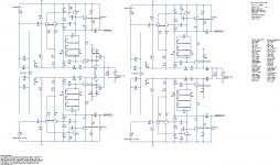
I have updated the model to show both channels. I doesn't show the optional NFB take-off point yet but I have added the cross-feed. It also needs an LED power-on indicator.
I've got two versions, one with cap multiplier and one with CLC. To get similar performance from the CLC I had to use 330mH on each rail. I could use larger caps.
The CLC is a bit cleaner. BUT my sims show something strange going on sub-10Hz, some kind of oscillation due to those inductors.
Model is attached...
Keantoken - I agree, nice to have H2 higher than H3, but even with the model I have attached, this seems to hold true. I really don't know how important the relative heights of H2 vs H3 are. Potentially this needs some prototyping to find out as the sims only go so far...
Attachments
You should include Hugh's input bias decoupling in the schematic. (I'm sure we're all agreed on this?)
Maybe I'm just blowing steam about the Jfet. I don't think it matters that much. I wouldn't know what it sounds like, either. A resistive bias network will be better at keeping the bias voltage at 1/2 rails, anyway.
I think we're about ready to make a prototype.
I like MJL's wall wart idea, but I don't like to carry wall warts everywhere and this thing wouldn't last very long on batteries... Perhaps we can add a "low bias" mode for using batteries?
- keantoken
Last edited:
Does anyone know first hand how it sounds? Has anyone built a prototype, or, is anyone planning to do it before the group buy?
We're getting there...
Unless there's a good deal for the boards, I probably won't build one, and I have my own design ideas anyways... Hehheheh...
- keantoken
Hey, Iko,
You are a bit optimistic!! Once the schemat is agreed to, a proto ratsnest will be built by one of us, then a good listen, then I have to do a pcb design (2 weeks, and quite a bit of time figuring all the options people want since this is a group project), then another 10 days turnaround for the pcb from China, then layout revisions after a further pre-production version is built and tested, and then the final 100 board manufacture - do you get the picture? This stuff is like breeding elephants, it takes a long time, all the more because it's not a money maker, so all that effort is gratis.
We should have a pre-production version up and running with about four weeks, but no sooner.
Kean, I will ensure you receive a board, and I will try to get the difficult bits to you as well. You are something of a local hero in these parts, and we need to look after you!
Say, anyone here know if there are any 2 x 30mH common mode chokes rated to 150mA easily available in the market? A rectifier bridge followed by C (cmc choke) C would make the best power supply in my opinion.....
Cheers,
Hugh
Last edited:
Say, anyone here know if there are any 2 x 30mH common mode chokes rated to 150mA easily available in the market? A rectifier bridge followed by C (cmc choke) C would make the best power supply in my opinion.....
Close, 28mH, 200mA
Cheap too.
Hey, Iko,
You are a bit optimistic!! Once the schemat is agreed to, a proto ratsnest will be built by one of us, then a good listen, then I have to do a pcb design (2 weeks, and quite a bit of time figuring all the options people want since this is a group project), then another 10 days turnaround for the pcb from China, then layout revisions after a further pre-production version is built and tested, and then the final 100 board manufacture - do you get the picture? This stuff is like breeding elephants, it takes a long time, all the more because it's not a money maker, so all that effort is gratis.
Cheers,
Hugh
I wouldn't say optimistic, rather, practical. I normally build a point-to-point circuit if it's small like this, before going to a pcb design, to iron out the wrinkles on the real thing. I've had enough surprises when going from simulation to reality to be cautious.
And I totally get the picture that anything looking like a proper pcb is still a way off.
To be honest, I am surprised that you're doing the pcb design for free.
Member
Joined 2009
Paid Member
Back to reality ... did some experiments on my TGM amplifier which tells me that the bias current in my sims is too 'hot'. The devices Hugh has selected for the output don't have metal tabs and we don't want to be worrying about heatsinks too much. Headphones aren't greedy, the worse case should be 23 Ohms.
I think your suggestion for the bootstrap take-off point is the better approach. It might be worth playing with the relative values of the bootstrap divider resistors to see if we have them optimized, I haven't looked at that at all yet.
[/url]
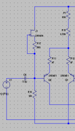
1: Choose bias current value, with which we determine net bootstrap resistance.
2: Choose cap size.
3: Then, we can choose bootstrap resistor values based on that. Increasing the lower resistor will increase load rejection of the bootstrap, but the cap will have to work harder through the top resistor, which will decrease bass rejection... So really this is a question of what kind of bandwidth do we want?
This is my "bootstrap optimization" procedure...
So, what is our bias current and what size cap can we use... Bigger is better, generally...
- keantoken
Last edited:
Member
Joined 2009
Paid Member
Sounds like a reasonable plan.
I would suggest that resistors are easy to change, their footprint on the pcb doesn't depend on their value, just power dissipation. The caps are more critical because their footprints depend on voltage rating, capacitance value and possibly manufacturer. I suggest a cap of 220uF would be a good value.
I would suggest that resistors are easy to change, their footprint on the pcb doesn't depend on their value, just power dissipation. The caps are more critical because their footprints depend on voltage rating, capacitance value and possibly manufacturer. I suggest a cap of 220uF would be a good value.
Member
Joined 2009
Paid Member
For different cap sizes, we could have a hole for one lead and a slot for the other so you can insert any size cap you want.
A nice bit of lateral thinking !
- but commercial pcb vendors like drilling holes. However, if we leave space for a large cap, a smaller one can have it's legs bent out to fit.
John,
Many thanks, that's a great choke, really impressive, cheap too!! Only 4R of series resistance, low losses!
Now, the biasing. How about three 4148 diodes to set the output stage bias at around 40mA?
Would that be OK?
And if we assume a max output of 12Vpp into 32R (that's 590mW) then the max current ever drawn by the load would be 6/32 = 188mA, and with 40mA bias the Class A zone would run out at 2.56Vpp, which is 25mW, plenty loud in fact if we assume 100dB/watt, around 70dBA sound pressure at the cans.
Since we are reading for 188mA max of output current, the transistors will need plenty of base drive. Assuming a beta of 150 for the 4793/1837 at 190mA (taken from the curves), we have a nominal base current demand of 1.25mA. The bias generator has no bias losses, unlike a Vbe multiplier, so 8 times this figure is reasonable for the VAS, and incorporates minimum delta I at the collector in all circumstances. This gives us 10mA collector current, which means bootstrap resistors, for a single rail supply of 24V, will be 470R and 680R (npv), as originally chosen. In fact with these values we shall have a VAS current of 9.5mA, which is close enough for government work......
Doing the pcb, IKO, will be a pleasure. I enjoy the work, it's relaxing.
Cheers,
Hugh
Last edited:
A nice bit of lateral thinking !
- but commercial pcb vendors like drilling holes. However, if we leave space for a large cap, a smaller one can have it's legs bent out to fit.
..Or we could just use one hole for one lead, and put a line of holes for the other lead. Same thing as the slot, really (Are you sure most PCB manufacturers don't do slots? It would be cooler).
Now, the biasing. How about three 4148 diodes to set the output stage bias at around 40mA?
Would that be OK?
And if we assume a max output of 12Vpp into 32R (that's 590mW) then the max current ever drawn by the load would be 6/32 = 188mA, and with 40mA bias the Class A zone would run out at 2.56Vpp, which is 25mW, plenty loud in fact if we assume 100dB/watt, around 70dBA sound pressure at the cans.
Since we are reading for 188mA max of output current, the transistors will need plenty of base drive. Assuming a beta of 150 for the 4793/1837 at 190mA (taken from the curves), we have a nominal base current demand of 1.25mA. The bias generator has no bias losses, unlike a Vbe multiplier, so 8 times this figure is reasonable for the VAS, and incorporates minimum delta I at the collector in all circumstances. This gives us 10mA collector current, which means bootstrap resistors, for a single rail supply of 24V, will be 470R and 680R (npv), as originally chosen. In fact with these values we shall have a VAS current of 9.5mA, which is close enough for government work......
Changes have been made to my schematic.
So, possible features:
1: Switchable crossfeed.
2: "Low bias" mode for battery operation (?)
Aren't I missing some? Perhaps a "line out" for use as a preamp?
- keantoken
- Home
- More Vendors...
- AKSA
- Aspen Headphone Amp