Hi Keantoken,
---Also, how about you try bootstrapping to Q7's emitter instead of to the output? This will make the bootstrap much more accurate. One transistor works more, but this should theoretically encourage even harmonics.---
Would doubling this with a second electrolytic connected to Q10 emitter be worth for linearity ?
I just checked in the simulator. I found very little affect (slightly positive) from changing between bootstraps to Q7 and/or Q10's emitter. In other amp simulations, I have noted that the harmonic spectrum changes significantly depending on whether you bootstrap to Q10 or Q7's emitter. I think this is worth experimenting with.
Also, the circuit has begun uncontrollably oscillating after I added series inductance to the caps and decreased the timestep. Increasing the miller cap didn't help, so it seems the problem is in the C-multiplier. I get the same oscillation whether or not I use the CFP c-multiplier. Just added some smaller bypass caps...
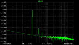
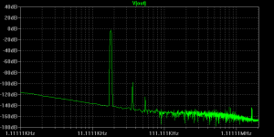
Okay, now look at this. The new bootstrap reference helps! 3rd harmonic is about 25db below the 2nd, whereas with normal bootstrapping it was 20db (I measured this at 20KHz since it gave a better FFT). (THD itself actually increases, but I prefer this because the spectrum is, by Hugh's logic, more benign). (I added a .four command to the schematic, results of which you can see in the error log)
Attached are old and new FFT's, and the .asc file used.
PS. I know the Jfet is funny and it can be done without (I agree with Hugh about bias decoupling). Also, the Vout node is before the output cap, since this gives better FFT. And for the record, the CFP C-multiplier can be done without, because the capacitors take care of PSU impedance in the audio range much better (CFP output impedance is about .078 ohms). I selected the caps by clicking "select capacitor" in the cap menu and then edited in my own estimated inductance values.
- keantoken
Attachments
Last edited:
Member
Joined 2009
Paid Member
Hugh,
I like the extra diode, from my thermal sims this is a safer option and ensures that the bias current will have a -ve thermal coefficient.
Good addition of the discharge resistor to the output cap - I was just about to suggest this (I remember it from NPs Zen amp) and of course as usual you are a leap ahead...
keantoken,
I'm disturbed by the problems with the cap multiplier. We should discard this if there is a risk. The psu needs to be clean and without regulators we need to ensure that channel-channel x-talk is kept low so that may mean dual supplies with passive filtering.
I need to look at those FFTs....
Well, we need to test the multiplier in real life. I think I'm doing this ESL thing wrong. Is it standard for capacitance multipliers to oscillate!? (by definition they should not, because they have no NFB. Of course, ESL adds a whole new dynamic to this)
I think we only need regulators to keep hum out, otherwise we can't get much better than the caps for load rejection. Why not power both channels from the same supply but with separate LC filters?
We could try boostrapping the LTP source in order to increase PSRR if we go without regulators.
- keantoken
Hugh,
I need to look at those FFTs....
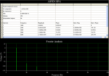
Here's what I get for Hugh's single supply model:
Attachments
Member
Joined 2009
Paid Member
I like the change in bootstrap, it keeps a bit H2 in there even at lower frequencies. This is something it would be nice to prototype, but my vote is in favour of your change.
Took me a second to remember you'd moved the OUTPUT to the 'wrong' side of the output cap - frequency response was great at 10Hz compared with my original sim
I've read headphones are pretty good at low frequencies, we should revisit the cap values.
For the cap multiplier, if we want to work that angle further, perhaps we should stick with the non compound version, keep it simple ?
Single supply still preferred. For my last project I used soft recovery diodes instead of the usual one-piece rectifier and CLC filters. No complaints about the results so far!
Hey Tess, sorry for being late. I have actually been putting together a reply. I had to reset my computer too, because the space bar was doing weird things...
- keantoken
Hi
No problem, I was just not sure that you've readed your PM messages.
Thanx
Paul
Member
Joined 2009
Paid Member
Here's what I get for Hugh's single supply model:
Looks to me like the THD is too low, we don't want this to sound like an opamp do we !? - let's get that H2 up...
I will offer pcbs through Gareth on a group buy basis, but I would discourage smd because assembly is a higher level skill not normally associated with DIYers. P-A's outstanding work gives some idea of how lovely it can look! I like the idea, I really do, but leaded components are more practical for small runs and inexperienced assemblers.
Cheers,
Hugh
Firstly, thanks for doing this Hugh.
I agree with the above quote. While I need to get sorted on using SMD, if this were an SMD board I probably wouldn't bother. Through hole I may be interested.
Cheers
Stuey
Looks to me like the THD is too low, we don't want this to sound like an opamp do we !? - let's get that H2 up...
Your enthusiasm is admirable, but it's harder than it looks.
Tess - I replied to your Email address.
- keantoken
Last edited:
Looks to me like the THD is too low, we don't want this to sound like an opamp do we !? - let's get that H2 up...
?
A distortion is the alteration of the original shape (or other characteristic) of an object, image, sound, waveform or other form of information or representation. Distortion is usually unwanted.
H2 is higher than H3, higher order are below -125db...this is good!
Sometimes we want distortion in order to cover up the nastiness of the equipment that recorded/mixed the music, or whatever digital processing was made. 2nd harmonics seem to be most pleasant, so "higher H2" might not be so bad.
This circuit doesn't have a problem with H4 and above, so then any further "tweaks" would probably be to improve the ration of H2 to H3.
- keantoken
This circuit doesn't have a problem with H4 and above, so then any further "tweaks" would probably be to improve the ration of H2 to H3.
- keantoken
Member
Joined 2009
Paid Member
yes it is looking good, very little distortion. On the other hand, many things in life are more interesting if they aren't too pure...
I guess we'd better remember it's for headphones, -100dB is a noticeable signal, whereas for speakers it's already buried in the noise.
I'm wondering about the output cap still, 470uF looks OK but not great - again I have read headphones can have really good LF extension - what do you guys think ? Would we be better off at 1,000uF or 2,200uF ?
Sometimes we want distortion in order to cover up the nastiness of the equipment that recorded/mixed the music,
I don't
I want to hear what was recorded faithfully.
My point is that the amp is exhibiting excellent qualities as is. I don't believe increasing distortion (even the "good" kind) will improve the sound.
For the cap multiplier, if we want to work that angle further, perhaps we should stick with the non compound version, keep it simple ?
This gets my vote. I don't see that a fancy regulator is needed, only to filter out mains noise.
- keantoken
what do you guys think ? Would we be better off at 1,000uF or 2,200uF ?
I would use at least 1000uF - it's what I have in the sim.
yes it is looking good, very little distortion. On the other hand, many things in life are more interesting if they aren't too pure...
I guess we'd better remember it's for headphones, -100dB is a noticeable signal, whereas for speakers it's already buried in the noise.
I'm wondering about the output cap still, 470uF looks OK but not great - again I have read headphones can have really good LF extension - what do you guys think ? Would we be better off at 1,000uF or 2,200uF ?
Better yet, why don't we take feedback from the output side of the capacitor, with a 10k pot coming from the other side of the cap to keep offset under control? This would help cancel any capacitor distortions and it would also extend the bass even with small capacitors.
EDIT: oops, this would work with a dual supply, but it could be tough with single...
As far as the bootstrap - It would be super easy to just put two different tracks on the PCB for both options. This would also help in prototyping.
- keantoken
Okay, here's my sim file. It's set up to run a response analysis - as you can see, the capacitor is compensated for (but because of single supply, I had to add another one..).
Downside to this is that the OPS has higher voltage swing at bass, so if the output cap is too small, we might actually clip.
- keantoken
Downside to this is that the OPS has higher voltage swing at bass, so if the output cap is too small, we might actually clip.
- keantoken
Attachments
- Home
- More Vendors...
- AKSA
- Aspen Headphone Amp