Member
Joined 2009
Paid Member
I will download shortly...Any problems with the capacitor producing phase shift to the feedback ?
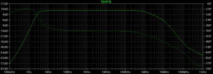
I just extended the AC simulation... It turns out this produces a ringing at 3Hz! This won't be stimulated by normal music, but it would ring for a few mS say, when you plug in the headphones. Hmmm...
EDIT: just found the solution: put a 1.5k resistor in series with C15. I guess this acts as a dampener... But it also seems to acttt as a sharp cutoff filter for frequencies below 5Hz.
 Maybe we should move this cutoff to 20Hz, just for conformity. (then again, do we want to be able to hit that "brown note"?)
- keantoken
Last edited:
A cap multiplier sim showing ripple reduction:

Orange trace is picked from the bridge rect at the first smoothing cap.
Scale is 50mV
Black trace is output from the cap multiplier.
Scale is 5mV
Blue is output from the amp into load with input shorted.
Scale is 5uV
Performance is quite good for this simple solution and I'm leaning toward this now myself.
I've been experimenting with the strange NFB arrangement...
I tried that before in another amp with terrible results. I just tried it again on this one and still, terrible results. It's a case of "If it ain't broke..." I think.
A Darlington should be safer than a CFP in this application.
The Darlington will also have the gain needed for the multiplier to be effective.
I'm trying to do a similar sim with the Jung super reg but I'm having simulation errors.
Member
Joined 2009
Paid Member
I've run quite a few sims on the cap multiplier over the past month as I try to learn how the Zen amp works. There are a few subtleties depending on your priorities - low or high current, sensitivity to drop-out voltage etc.
I understand Hugh has tried them in the past and isn't a big fan of them in terms of the sound. Plus, he may be willing to share some wisdom from his other high-end power supplies in terms of optimal filtering. So the Jury is still out I guess.
I understand Hugh has tried them in the past and isn't a big fan of them in terms of the sound. Plus, he may be willing to share some wisdom from his other high-end power supplies in terms of optimal filtering. So the Jury is still out I guess.
Member
Joined 2009
Paid Member
I just extended the AC simulation... It turns out this produces a ringing at 3Hz! This won't be stimulated by normal music, but it would ring for a few mS say, when you plug in the headphones. Hmmm...
EDIT: just found the solution: put a 1.5k resistor in series with C15. I guess this acts as a dampener... But it also seems to acttt as a sharp cutoff filter for frequencies below 5Hz.
- keantoken
Well I've dug up some frequency response curves for a couple of headphones. It doesn't look as if there's much benefit from extending the frequency response below 20Hz.
Can you weight up the benefits of NFB before vs after the output capacitor in terms of parts count, distortion, phase response ?
My thinking is that some folks like the NFB after the cap, figuring that it helps to reduce any distortion arising from the cap it'self. But I'm not old enough to remember the poor caps from 40 years ago - modern caps are so much better.
Attachments
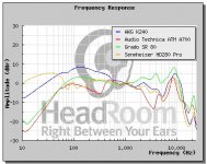
Well I've dug up some frequency response curves for a couple of headphones. It doesn't look as if there's much benefit from extending the frequency response below 20Hz.
Can you weight up the benefits of NFB before vs after the output capacitor in terms of parts count, distortion, phase response ?
My thinking is that some folks like the NFB after the cap, figuring that it helps to reduce any distortion arising from the cap it'self. But I'm not old enough to remember the poor caps from 40 years ago - modern caps are so much better.
With NFB after the output cap, there is no benefit except in bass response. There is an odd ringing that happens at 5Hz which, if too large, might overstress the headphones.
I'm sure it would work much better if we were using a dual supply (but then we wouldn't need it). I don't think it is practical for our application.
- keantoken
Member
Joined 2009
Paid Member
Keantoken - I suggest we follow your caution and keep the NFB before the output capacitor.
Now, changing topic again to the subject of Crossfeed. Headphone amps need a switcheable cross-feed between channels, at the input. I am assuming that we'd place the associated components at the switch itself rather than on the pcb - any thoughts on this ? - this gives people the choice to include or not to include it.
Now, changing topic again to the subject of Crossfeed. Headphone amps need a switcheable cross-feed between channels, at the input. I am assuming that we'd place the associated components at the switch itself rather than on the pcb - any thoughts on this ? - this gives people the choice to include or not to include it.
I think it is a good idea.
It doesn't need to be this complex, does it?
http://www.headwize.com/projects/meier_prj.htm
- keantoken
It doesn't need to be this complex, does it?
http://www.headwize.com/projects/meier_prj.htm
- keantoken
Member
Joined 2009
Paid Member
If we had a standard enclosure we could put almost everything on the board, but it would require everyone to use the same parts and whilst this would be good for a kit, I don't think that's what Hugh has in mind.
A separate board is possible, but it adds to the complexity, Hugh is only going to make one pcb, it will have both channels on it.
We could pick one edge of the pcb to be at the chasis edge and onto this edge we could have pcb mounted connectors/switches if we wanted to.
We could also make the switch one of those pcb mounted DIP switches and it could be accessible from a small hole in the chasis. Not convenient if you want to change the setting often but quite good enough if you usually keep it at one setting. And lower cost too.
We need to boil this thread down to a reference design and a BOM.
Last edited:
Member
Joined 2009
Paid Member
OK, so let's post a reference schematic that includes the cross-feed, all the swtiches and connectors. The power supply is still tbd. The options seem to be a) cap multiplier, b) CLC. Hugh is leaning towards CLC.
I'll help compile a BOM based on digikey.
(gotta go, movie starts soon...)
I'll help compile a BOM based on digikey.
(gotta go, movie starts soon...)
It doesn't seem like hum is a problem in Hugh's other amplifiers, which are not headphone amps. So it should be possible to get satisfactory performance without the regulator. So I could go either way.
There is one thing I want to make note of. A Jfet current source has somewhat poor PSRR, but it adds plenty of H2. Recall the input bias configuration I used. It actually increases H2 in the simulator. Should we try it?
- keantoken
There is one thing I want to make note of. A Jfet current source has somewhat poor PSRR, but it adds plenty of H2. Recall the input bias configuration I used. It actually increases H2 in the simulator. Should we try it?
- keantoken
- Home
- More Vendors...
- AKSA
- Aspen Headphone Amp