P-A,
Agree with you emphatically.
That's the reason the voltage amplifier is npn. All the others are either EFs or ancilliaries.
V1 is a simulated AC voltage source for test purposes. It's an integral part of LTSpice, of course. C3 is simply the fb shunt cap to ground.
I'll email the other circuits to you tomorrow, my apologies for delay, and my thanks for your expert input.
Hugh
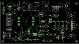
Eagle has been my choice of PCB software lately and I greatly enjoy the using the software to make PCB layouts. Which brings me back to this amplifier. I believe that there hasn't been a PCB made for it yet, and I offered a while back to make a layout, but i was discouraged because of the confusing schematic. Things make a lot more sense now.
If i could get someone much more knowledgeable to let me know if i recreated the schematic correctly within eagle, I could begin on both a one sided layout and a double sided with silk etc. For a possible group buy PCB.
Would a companion PSU be favored also?

If i could get someone much more knowledgeable to let me know if i recreated the schematic correctly within eagle, I could begin on both a one sided layout and a double sided with silk etc. For a possible group buy PCB.
Would a companion PSU be favored also?
When you mean differentiate you refer to using star ground?differentiate between Signal Ground and Power Ground.
Add an on board single polarity supply with a virtual ground.
Does this virtual ground look good? Disregard C1 and C2 values.
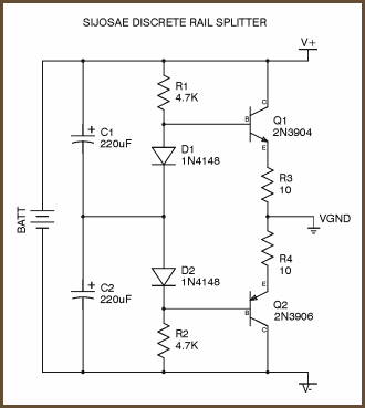
I assumed that was the value of the R3 resistor since that's what it appears to be on post #1037.R3: what does mean 1020.30 mean?

Member
Joined 2009
Paid Member
I'm glad some interest is returning. The more I work on the PCB, the more fun it is, playing with this and that. Are power planes OK?
 ,
,
The golf islands are a chain of islands around the larger Vancouver island on the Canadian side of the boarder, the other islands on the American side are called the San Juan islands, which is where I actually ended up going. To a island called Sucia (Su-Sha), lovely hiking:
Sucia Island State Park, WA, United States - Google Maps
Reversed cf? Direction?C1V & C2V reversed cf. the other 5 electrolytics.
Are you asking me to put extra vias to allow for different diameters of capacitors? I haven't processed a BOM, so most of the components are relatively "eyeballed" based on the value of the component.Can extra pin pitch options be added to all capacitor locations? C2 & C5.
Nope no golfEnjoy that golf!!
, The golf islands are a chain of islands around the larger Vancouver island on the Canadian side of the boarder, the other islands on the American side are called the San Juan islands, which is where I actually ended up going. To a island called Sucia (Su-Sha), lovely hiking:
Sucia Island State Park, WA, United States - Google Maps
Attachments
Yoyo KofA, I have a question:
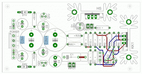
One channel per board? I like it, I'm all for dual-mono, but this'll make any tone control a little harder, and implementing the crossfeed will mean bringing both of these boards back to some 3rd common board before output. Most people's headphones will have a common ground in their jack anyway, so would a stereo board not avoid ground loop issues too? EQ and crossfeed are not such big issues for me but I think that we want our phones to come back to a star ground which would best be on a stereo board.
I don't mean to put you off the effort, you're a champion for doing this for us ;P
--dwf
Yes, echo that dwf - and maybe extra options for all the caps, not just the electros.
Hi KoA, it's coming together nicely.
I don't know if your program allows for it but having the plane so close to the donuts and those thin tracks is a nightmare if you want to make changes to the cct, or just add components like parallel resistors, caps, etc - can this small clearance be increased so a good gap is between and increase the width of the tracks?
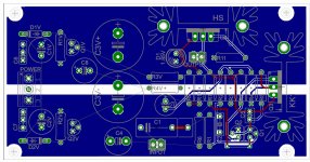
A suggestion: It seems you have used the gnd plane as a common 0Volt "point" - suggest discrete tracks to create a "centre star" instead, to control individual 0volt return paths - might need to move some of the bottom/lower level tracks to the top.
... just my 2 cents
Hi KoA, it's coming together nicely.
I don't know if your program allows for it but having the plane so close to the donuts and those thin tracks is a nightmare if you want to make changes to the cct, or just add components like parallel resistors, caps, etc - can this small clearance be increased so a good gap is between and increase the width of the tracks?
A suggestion: It seems you have used the gnd plane as a common 0Volt "point" - suggest discrete tracks to create a "centre star" instead, to control individual 0volt return paths - might need to move some of the bottom/lower level tracks to the top.
... just my 2 cents
For the record, I'm willing to take the time out of my school, and out of my life to make this what it needs to be, and no less. I need to do the absolute necessary to build this board layout into what is absolute necessary, So please keep the suggestion coming. They won't ever offend me as long as they bring and a maintain constructive environment around this project. And for future reference, please call me kurt
@derwhalfisch: When i first started building the actual board layout in diptrace, I had two channels on one board, I first found it over whelming, but that was a while ago. I'll put two channels on one board so set up a proper star ground of sorts to simplify the wiring layout, and I understand how important that is. I'm glad i took a bit of a breather to spend sometime working on my dynalo, and I learned some excellent lessons (although the dynalo still doesn't work, but that's beside the point), on proper board layouts. Mostly wiring schemes and powersupplys. So yes I'll incoperate the proper star ground for TRS style jacks. Also note that the two blue planes are power-planes and not ground-planes
@jameshillj: Like I said above, the two blue planes are infact powerplanes, I've hidden the ground plane in the top layer for the pictures, but otherwise it's only there to simplify the ratsnest of hell that the extra traces that I shouldn't be worrying about at the moment. The finalized boardlayout will have a ground plane in the top layer, but it will be connected to a one separate point, rather then being connected to all. I can adjust the clearance for the planes, and i might end up adding quite a bit of clearance for the traces, having such a small gap tends to add to errors in the manufacturing processes. I'll also change the width of most of the traces on board to be on par with the schematic. I could try and add additional vias for modding a CCT a easier job, creating something modular seems to be popular in DIY.
Would anyone like to help me collect a BOM together? I could start some kind of google document so collaboration could be done?
Would there also be any interest in a superjung regulator board as a PSU? and possibly a filter section too?
Last edited:
Kurt,
This board is coming along very well. A good board takes tens of hours. I've spent hundreds on boards, it's a huge undertaking, but fundamental to any product. You are learning real fast and doing a fantastic job, so please, keep it up.
Once you have the board 90% complete, you should set it aside and stare at it quietly each night for half an hour before you retire. It is amazing how layouts gel in the mind during a period of sleep, giving you fresh ways of approaching things the next morning. If this sounds obsessive, it's probably because it's the obsession that makes the product exceptional.
I am a bit leery of tone controls, but all for crossfeed. My opinion only; don't let me stop you there. But there is quite a bit of additional complexity required.
I would not use a feedback power supply for this HPA. I would use a simple emitter follower, series feed, using a zener diode as the reference. Simpler, and sounds better IME. It's not precision you need, it's stability and transient response.
I can help with the BOM, email me privately through my website.
Thank you for doing such a sterling job, much appreciated, I'm very busy at present,
Cheers,
Hugh
- Home
- More Vendors...
- AKSA
- Aspen Headphone Amp