Member
Joined 2009
Paid Member
I suggested adding ESR for the sake of simulation - ESR can have a large affect in the simulator and I think this is important to note.
As I said, I have an open mind, am willing to learn, but perhaps lazy to do the work

If we want an exotic volume control we can try a lamp and a CdS photoresistor... Do you not want to use a simple POT?
I was very interested in the LDR approach by georgehifi [http://diyaudioprojects.com/Forum/viewtopic.php?f=12&t=615] - it has received a lot of interest. It is another layer of complexity and the issue of matching etc. with these components makes the design a little less 'universal' for people to build so although I may try it myself one day, it's probably not an ideal choice for an Aspen product.
Hugh has usually recommended cermet faked-law pots. My experience is limited to the P9 vishay conductive plastic pots on the amplifier input and it sounded fine to my ears.
I'd be interested in other's thoughts on this ?
you can manyfold decrease PSU ESR by using a CFP pass transistor configuration (this works because the slave transistor divides the master's transconductance which determines Ic vs. Vbe).
Interesting idea, I like CFPs. What level of PSRR do you think we need ? - no point chasing this beyond what is necessary.
[p.s. I'm off to sleep now...]
The truth is that for diy purposes it's easy enough to try a few output caps on a regulator. The rule of thumb is that it should not have too low ESR.
The bigger uglies to deal with to aim for a stable circuit will be the board layout and phase shift in the dc amplifier. That is, if you aim for a low impedance in the higher frequency range.
The bigger uglies to deal with to aim for a stable circuit will be the board layout and phase shift in the dc amplifier. That is, if you aim for a low impedance in the higher frequency range.
I will look at that app note (thanks for your input). Although I don't think we need to worry if we are not going to go beyond a series capacitance multiplier. I don't presume the Tunnel of Death is a hard-fast rule since it will probably depend a lot on the frequency characteristics and internal compensation of the regulator used.
I have no idea how much PSRR we need (cough cough), not really sure of the sonic benefits there, with the exception of noise which is related to line rejection and not output impedance. (should we consider it good if we get the pass transistor to have lower ESR than any decoupling cap we use?)
Also, "signal decouplers" become increasingly useless as they have higher ESR than the regulator. So do we want a low-ESR reg that sinks the signal, or higher-ESR reg that takes care of bass and decouplers that take care of the signal? Either way it should be good to have some form of HF decoupling.
Good idea Bigun, I'm going to sleep too.
If log is a problem, why not do this? I think going for exotic volume control is a bit over the top...
http://sound.westhost.com/pots.htm#chg-law
- keantoken
I will look at that app note (thanks for your input). Although I don't think we need to worry if we are not going to go beyond a series capacitance multiplier. I don't presume the Tunnel of Death is a hard-fast rule since it will probably depend a lot on the frequency characteristics and internal compensation of the regulator used.
Exactly. One must do a stability analysis of the specific circuit under consideration. Recommending CFPs for regulators is going way out on a limb unless a careful stability analysis has been done. You have done such a stability analysis, right?
At any rate, the inductance of an electrolytic cap will dominate its impedance above a couple hundred kHz or so. Suggesting to people to extend their simulation to 1 GHz, while neglecting the inductance of the capacitor is going to give totally wrong results. SPICE semiconductor models aren't much good at 1/10 of that frequency, not to mention other problems as well.
Last edited:
Hi Keantoken,
---Also, how about you try bootstrapping to Q7's emitter instead of to the output? This will make the bootstrap much more accurate. One transistor works more, but this should theoretically encourage even harmonics.---
Would doubling this with a second electrolytic connected to Q10 emitter be worth for linearity ?
Hi Hugh,
---I'll redo the single power supply design, Forr!---
All I suggest is mainly ideas for easily done experimentation, not necessarily to be adopted.
Since this is JUST a little headphone amp/ preamp? , why not "think out of the box" with its construction ??

Quite likely , on both this pre/HF amp AND the input diff./ cascode of my "supersym" , I will use SMD. In fact , I am planning to replace just about anything that has a SMD equivalant except for VAS'es ,OP stages,Cdom and input cap.
Take a look at the fine BC846 dual (matched) PNP package : http://www.mouser.com/ProductDetail/NXP-Semiconductors/BC846BS115/?qs=sGAEpiMZZMuCl5o%252b/AuPoM4U4Er2UbljNaA5o/Jf0uM%3d
Specs out nice against the 2n5401 (better even + it is matched) , would also work nice on a cascoded "big amp" as well . I could most likely get this down to a 1" X3" (or 1 X 4/5" for stereo) , reducing parasitics and the "footprint". SMD resistors and small caps are of better tolerances as well and not as hard to work with as might be thought.
OS
Quite likely , on both this pre/HF amp AND the input diff./ cascode of my "supersym" , I will use SMD. In fact , I am planning to replace just about anything that has a SMD equivalant except for VAS'es ,OP stages,Cdom and input cap.
Take a look at the fine BC846 dual (matched) PNP package : http://www.mouser.com/ProductDetail/NXP-Semiconductors/BC846BS115/?qs=sGAEpiMZZMuCl5o%252b/AuPoM4U4Er2UbljNaA5o/Jf0uM%3d
Specs out nice against the 2n5401 (better even + it is matched) , would also work nice on a cascoded "big amp" as well
. I could most likely get this down to a 1" X3" (or 1 X 4/5" for stereo) , reducing parasitics and the "footprint". SMD resistors and small caps are of better tolerances as well and not as hard to work with as might be thought.OS
Member
Joined 2009
Paid Member
??? is that sarcasmBy bigun - I'm not set up for Lillput electronics
seriously , you don't have to be set up for it. a very small dab of glue , stick it on , 6 quick needle tip solder "shots".. done !! It is actually easier than sticking 6 leads through the board (no drilling as well)

You can build whole complex input stages for pennies on small boards and have 1-2% tolarances as the norm . win-win proposition.
By MJL - There is also the DMMT5401 in the SOT-26 package. Similar specs at a higher voltage. These are available at Digikey.
And they have the 5551's (npn) as well
,also ..<2% thermally coupled and hfe matched.Enter the "postage stamp input stage"
and the "postage stamp super reg" for low current circuits , space is no longer a consideration.
OS
Member
Joined 2009
Paid Member
seriously , you don't have to be set up for it. a very small dab of glue , stick it on , 6 quick needle tip solder "shots".. done !! It is actually easier than sticking 6 leads through the board (no drilling as well)
Ok - well, it will be a new adventure
I'll redo the single power supply design, Forr!
Hugh
Sir
Single supply design are ok for me.
Thanx
Paul

Member
Joined 2009
Paid Member
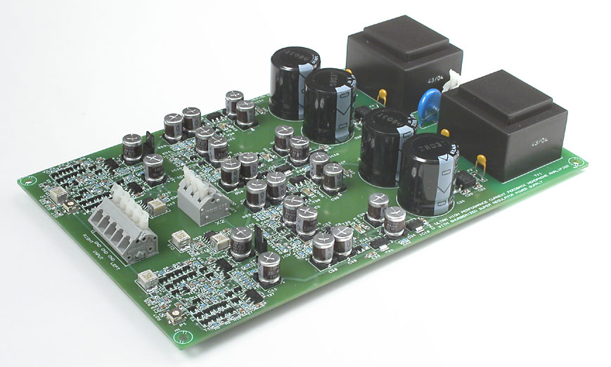
Nice photos.
But I'm still reluctant despite the eye candy...
Whilst parts are still available (one day they may not) I'm very tempted to stick with through-hole as much as possible, for me it's the last hold out in electronics where we can still play with real parts, make pcbs, handle things, construct things with an unaided eye, and make things that look 'crafted'
I guess we should make sure the parts are big enough to suit a range of DIY skills so that we get a good take-up of boards (no 0402's ?).
Last edited:
Member
Joined 2009
Paid Member
Well Per, that's very nice work. It looks like you've done a very nice job.
At my day job, we manufacture products that are deep into SMT, 0201 parts are so small they can't be labelled. You can't really hand solder them, even with a microscope
You have to be careful with cleaning, if you can use 'no clean' solder then all the better, otherwise it's easy for flux to get trapped around small parts. These things are carefully controlled for quality.
So when it comes to hobbies - well, this is why I like those nice thro-hole pieces. But I guess even hobbies have to move with times and soon we won't be able to buy what we need as a thro-hole part perhaps ?
Last edited:
Member
Joined 2009
Paid Member
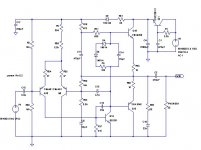
Single Supply... single rail cap. mux (optional), PSRR looks like at it reaches -100dB around 200Hz and gets better after (depending on you assumptions about inductances and capacitances of course).
Do we have (or need) models for the SMT parts or are they equivalent to the thro-hole ?
Do we have (or need) models for the SMT parts or are they equivalent to the thro-hole ?
Attachments
Gareth,
I like it - very nice, though the input divider could be decoupled for slightly lower noise.
I will offer pcbs through Gareth on a group buy basis, but I would discourage smd because assembly is a higher level skill not normally associated with DIYers. P-A's outstanding work gives some idea of how lovely it can look! I like the idea, I really do, but leaded components are more practical for small runs and inexperienced assemblers.
Cheers,
Hugh
Attachments
Last edited:
- Home
- More Vendors...
- AKSA
- Aspen Headphone Amp