Also, how about you try bootstrapping to Q7's emitter instead of to the output? This will make the bootstrap much more accurate.
Hi Kean,
I tried something similar to this on my patchwork amp and liked the results. It was recommended by jcx (knows his stuff for sure) and displayed a marked reduction in the simulated THD.
My thoughts on regs are in line with my thoughts in general on power supplies: have on hand more than you need. this applies to voltage and current. For instance - if the amp is designed for peak power output from a supply voltage of 15VDC, have 20VDC on hand and reduce gain. This allows for built in headroom for clipping and has the reg working in it's most linear region. Does this make sense?
Member
Joined 2009
Paid Member
Thanks John, Gareth, OS,
Good ideas all round.......
One further to muse on. If we make the amp single supply, it will be cap coupled, and that throws up the wooden cross for most here. However, there are three advantages. One, the supply is simpler, two the cans have automatic DC protection, and three, a substantial DC bias across a cap makes it sound way better.
The input cap on any bipolar supply power amp typically has around 0.1 volts across it. Only a very good cap sounds any good in this position, and that's expensive. I often use Sonicap, and they cost an arm, leg, and left kidney.
Thoughts before we start on a pcb design?
Cheers,
Hugh
As you know, my vote is for simplicity so a single supply would get my support.
I view that the signal ALWAYS passes through a capacitor. You can avoid putting one at the amplifier output, but you will still have one on the power supply unless it is a battery (and a battery is a big capacitor
 ).
). If any of the psu is going on the main pcb I would suggest you allow some space on the pcb for people to choose a capacitor that lets them feel good about all the $ they spent on it or the option for a less expensive one for those that can't hear the difference. In general, caps come in different shapes and sizes, good to allow some flexibility.
I'm not against regulators, but I'll play Devil's Advocate and vote against !
I still like the idea of a single pcb with all on-board, including the psu (cap multiplier). This would mean people who want to go the whole hog with an off-board regulator would leave some parts on the main pcb un-populated.
Connectors - we don't have Amps here, so big spade lug connectors may not be needed. We have the option of multi-pin headers for tidy connections.
Heatsinks - don't need to be large, can we use clip on heatsinks for individual devices ? If possible, the output devices should not be on the same heatsink, this allows them to be mounted without insulating pads - the heatsinks connect with the device collectors and float at the rail voltage. With a single supply at least half of them are at ground. This reduces thermal resistance.
Volume control anyone ?
Last edited:
Hi Kean,
I tried something similar to this on my patchwork amp and liked the results. It was recommended by jcx (knows his stuff for sure) and displayed a marked reduction in the simulated THD.
My thoughts on regs are in line with my thoughts in general on power supplies: have on hand more than you need. this applies to voltage and current. For instance - if the amp is designed for peak power output from a supply voltage of 15VDC, have 20VDC on hand and reduce gain. This allows for built in headroom for clipping and has the reg working in it's most linear region. Does this make sense?
Current draw should matter more than the actual regulator voltage (although if HV transistors are required BW might suffer unless they're Japanese). Your supply should at least be robust enough not to pop on the max transient, or if it breaks and shorts. (I might not understand what you're really trying to say)
For me, operating series reg "well within limits" means that I must look at the Ic vs. Hfe curve for the pass device: output current should only on transients go beyond the "crest point" where the OP's gain begins to drop. This will inject strange harmonics into the output. You should also not operate it at low enough current that it causes error (if you are using a darlington or CFP output configuration, the slave device will turn off of you're drawing too low current (or the VAS might turn off too), which will cause switching-like errors).
I agree that there should be room for clipping too. Besides, if we look at amplifiers as an art rather than utilities, it makes sense not to use "only what is required". Long ago designers weren't so conservative, one of the reasons I believe some of that stuff lasts for ages.
I really like AKSA's reasoning on a single PSU (regarding input cap)... That's my vote. (although perhaps we could still use dual supply, but only use it for the output, so the benefits of biased input cap is still there).
- keantoken
Last edited:
Member
Joined 2009
Paid Member
A dual supply is not such a PITA, it doesn't mean we have to use dual bridge rectifier, we could use a centre-tapped trafo. It keeps the feedback servo intact.
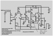
Anyhow, thinking of adding a dual rail capacitance multiplier and looking at the PSRR between the psu input and the amplifier output...I tried a simple simulation. Hope it isn't wrong.
p.s. OK, I am a bit biassed (one of my new DIY projects at home will use a cap multiplier)
Anyhow, thinking of adding a dual rail capacitance multiplier and looking at the PSRR between the psu input and the amplifier output...I tried a simple simulation. Hope it isn't wrong.
p.s. OK, I am a bit biassed (one of my new DIY projects at home will use a cap multiplier)
Attachments
Last edited:
Add some series resistance to the 470uF caps, to make it more realistic. How about .006 ohms (I think this is a believable value).
Also, plot the phase as well - this may help.
A Zener across the cap will improve line regulation.
To reveal more of the spectrum, simulate to 100MHz or even 1GHz. Then you will see the actual effect of the 470uF decoupling caps.
- keantoken
Also, plot the phase as well - this may help.
A Zener across the cap will improve line regulation.
To reveal more of the spectrum, simulate to 100MHz or even 1GHz. Then you will see the actual effect of the 470uF decoupling caps.
- keantoken
Member
Joined 2009
Paid Member
Add some series resistance to the 470uF caps, to make it more realistic. How about .006 ohms (I think this is a believable value).
Also, plot the phase as well - this may help.
A Zener across the cap will improve line regulation.
To reveal more of the spectrum, simulate to 100MHz or even 1GHz. Then you will see the actual effect of the 470uF decoupling caps.
- keantoken
Good idea - I should add some ESR to the caps.
The plot already shows phase (dashed line).
I don't like Zener diodes, dirty things.
p.s. I view the 470uF caps as the path taken by the signal, so we should think of them as more than decoupling capacitors.
Last edited:

I don't like Zener diodes, dirty things.
p.s. I view the 470uF caps as the path taken by the signal, so we should think of them as more than decoupling capacitors.
Why no zeners?
That makes sense. So in order to see the effects of the caps WRT signal, why not put the AC source in the amplifier input and plot the current through the caps. I'm somewhat skeptical of the caps' affect at audio frequencies... In my experience they are only large enough for decoupling. I'm not saying they're not needed or that they have no affect. Rather, I think they should be larger.
- keantoken
Member
Joined 2009
Paid Member
Member
Joined 2009
Paid Member
Why no zeners?
That makes sense. So in order to see the effects of the caps WRT signal, why not put the AC source in the amplifier input and plot the current through the caps. I'm somewhat skeptical of the caps' affect at audio frequencies... In my experience they are only large enough for decoupling. I'm not saying they're not needed or that they have no affect. Rather, I think they should be larger.
- keantoken
I don't have enough experience to know what size they should be, generally smaller means lower ESR. The reason I see them as part of the signal circuit is that the a.c. currents flowing through the load will flow through the output devices of the amplifier and then through the psu and I view that the lowest impedance path for the audio signals through the psu will be through these capacitors rather than through the cap. multiplier ????
Zeners are silicon used under duress, it's cruel. Operating in a constant state of breakdown (or tunneling straight through them). They must scream out in protest. Mostly at high frequencies perhaps.
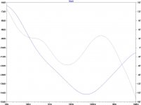
Here's an extended freq. range and a comparison between zero ESR (blue) and 6mOhm of ESR (green).
Maybe this is good enough ?
Adding to my last post (I posted just a second before you posted), how about also a plot of output impedance (,PSU output voltage / PSU output current).
The roll off after 10MHz is (unless I'm wrong) because of the 470uF "signal decoupling" capacitors. This is why I question their affect at AF.
- keantoken
Last edited:
If you're interested in finding out about modeling of real-world capacitor impedance, you should check out the Cornell-Dubilier application note, Improved SPICE Models of Aluminum Electrolytic Capacitors for Inverter Applications. One thing they say is, "Typical series inductance values of radial and screw-terminal capacitors are about 1-2 nH/mm terminal spacing". Also, the ESR of these types of capacitors is going to be something along the lines of 0.1 to 0.2 Ohms. As well, have a look at Kemet SPICE. Unfortunately, that one only works with tantalum and ceramic capacitors, but it's interesting to see the kind of models it comes up with.
Last edited:
Member
Joined 2009
Paid Member
Sorry guys - I don't think I'm doing you a good service with my sims quite yet although I do like doing them.
First off, I have to transfer files back and forth between a PC laptop and my iMac in order to post results, which is a bit of pain.
Secondly, having read a few threads over the past weeks I've seen a level of expertise that makes me look like a medieval knight, whereas people like Keantoken and Andyc are better examples of Merlin
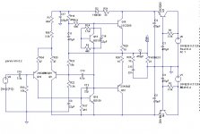
So here's the file I've been using... please post back if you make improvements and perhaps somebody can update the models to match the devices Hugh has selected ?
[change .txt to .asc to use the file]
First off, I have to transfer files back and forth between a PC laptop and my iMac in order to post results, which is a bit of pain.
Secondly, having read a few threads over the past weeks I've seen a level of expertise that makes me look like a medieval knight, whereas people like Keantoken and Andyc are better examples of Merlin
So here's the file I've been using... please post back if you make improvements and perhaps somebody can update the models to match the devices Hugh has selected ?
[change .txt to .asc to use the file]
Attachments
Hugh said you should lead this thread. He seems to trust your skill, something that shouldn't be underestimated.
People like me who obsess over details might not be good to rely on for design changes...
It's the sound that we're looking for. So maybe you should build it now with a versatile board and THEN try different supplies, etc. Then there's not so much need for technical input.
I will look at that file.
BTW, I think the 5200/1943 for the pass transistors is overkill... You could get away with say, BD139/140 I think, to cut down costs.
- keantoken
YukkBy KeanToken - Why no zeners?
shunting to ground ,I assume. I have seen Zener circuits last 17 years (bass amp I just fixed). They are the same in theory as a BJT or IC reg shunting to the load , but they are noisy. Everyone is "jumping ahead" , I am still on the amp. Are you all going to use a active or 2 diode Vbe ? run it class A or B ? (lowest = .02% at 125ma class A- MJE's)
To keep it simple , I have gravitated toward the (2)1n914's (on the main HS) + a 500R trimmer w/ 22u decoupling cap. At least in class A , this would do well for thermal stabilization. At 125ma per device @ 1/2 amp total , just a 1 1/2" X 6" angle with the diodes and OP's attached to it would work out good.
BTW , I am keeping it dual supply and using IC regs. (same as the DACS that will be with it). Final prototype (as I will make it) attached.
OS
Attachments
Member
Joined 2009
Paid Member
Hugh said you should lead this thread. He seems to trust your skill, something that shouldn't be underestimated.
People like me who obsess over details might not be good to rely on for design changes...
It's the sound that we're looking for. So maybe you should build it now with a versatile board and THEN try different supplies, etc. Then there's not so much need for technical input.
I will look at that file.
BTW, I think the 5200/1943 for the pass transistors is overkill... You could get away with say, BD139/140 I think, to cut down costs.
- keantoken
Technical input is good, otherwise we don't get the fun of debating the design
And yes, to be honest, I'm not too concerned over the small details in terms of the capacitor esr - BUT some of you guys are and why take the fun out of it by me pouring cold water on it - if you can take the simulation file and explore some avenues I'm not interested in then do so, I may learn something new ! .... the high sensitivity of headphones does scare me though.
I used 5200/1943 because I have spice models for them; I don't have models for the driver devices Hugh uses (yet).
Any thoughts on volume control ?
Member
Joined 2009
Paid Member
Yukk
Everyone is "jumping ahead" , I am still on the amp. Are you all going to use a active or 2 diode Vbe ? run it class A or B ? (lowest = .02% at 125ma class A- MJE's)
To keep it simple , I have gravitated toward the (2)1n914's (on the main HS) + a 500R trimmer w/ 22u decoupling cap. At least in class A , this would do well for thermal stabilization. At 125ma per device @ 1/2 amp total , just a 1 1/2" X 6" angle with the diodes and OP's attached to it would work out good.
BTW , I am keeping it dual supply and using IC regs. (same as the DACS that will be with it). Final prototype (as I will make it) attached.
OS
I like the diodes. I simulated the temperature sensitivity. With the Vbe multiplier there's a clear negative thermal feedback and the current through the output emitter resistors drop when the heatsink temperature rises. With the two diodes it's close to neutral, and actually my sims showed a very small increase in output current with a rise in temperature - probably not enough to worry about though. But the ability of the diode's to control the temperature coefficient does depend a little on the value of the resistor - I used 180R as you suggested.
I agree with you, at these relatively low power levels, it would be a crime not to run it ClassA, at least for headphones of 23 Ohms and above, within reasonable listening levels.
I suggested adding ESR for the sake of simulation - ESR can have a large affect in the simulator and I think this is important to note.
If we want an exotic volume control we can try a lamp and a CdS photoresistor... Do you not want to use a simple POT?
And, for the record, you can manyfold decrease PSU ESR by using a CFP pass transistor configuration (this works because the slave transistor divides the master's transconductance which determines Ic vs. Vbe).
I share your thought that the signal should go through a capacitor. However, this is only practical if the capacitor has lower ESR than the PSU - otherwise, the PSU will sink most of the signal anyways. So decreasing the ESR of the PSU might be a bad thing (although some real-life testing may be in order for this).
- keantoken
I suggested adding ESR for the sake of simulation - ESR can have a large affect in the simulator and I think this is important to note.
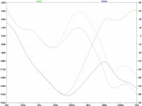
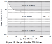
It ain't just the simulator. It's the real world. ESR (and also ESL) is very important for voltage regulator stability for example. See the discussion of the "tunnel of death" as it applies to regulator stability in this TI app note. It's given this name because if the ESR is too big, the regulator will be unstable. Likewise, same deal if the ESR is too small. The graph below shows one particular example.
That's why it's important to scour app notes and data sheets to get the best values you can, as opposed to pulling numbers out of the air.
Attachments
- Home
- More Vendors...
- AKSA
- Aspen Headphone Amp