Member
Joined 2009
Paid Member
What is the purpose of a zobel network and for what load is it designed or is its purpose just to shunt some oscillation and at what frequency seeing that we have headphones varying in impedance from 23 ohms to 500 ohms. Nobody questions these things and take it for granted.
Good point, we've not looked at the Zobel once. In fact I think I removed it from my sims at some point. I guess we need to ask what range of headphones we are trying to deal with and whether they have very much reactance ? Is it safe to say that headphone cables are reasonably well behaved ?
Hi Guys,
would anybody care to check the bias values? It seems that the amp output is sitting around 10 volt, I think it would be best to sit around 12V, or supply/2.
Also since the amp is now AC output coupled, the bias pot might as well be a fixed resistor at some convenient value, say 1k, and then make the 5K bias resistor variable, would you agree?
Circuit so far...
Notes:
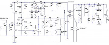
Based on this schematic, the latest at post #440, we have:
1. Voltage divider based on R29 (5K) R16 (10K) and R12 (12K). I propose that R29 be deleted, R16 remain at 10K, R12 at 12K, and a single resistor of 33K be taken from the midpoint of R16/R12 to the base of Q3. The present C15 can then be moved to the junction of R16 and R12.
2. R11 affects the sonics. It reduces the decoupling of C14, and permits the bootstrap node at the cathode of D5 to vary stage current of the LTP via R15/preset. I suggest this should be reduced back to the original 33R.
3. It may be that C6 is too small, and may require increasing to around 22pF. This to be established at prototyping stage. Reason: single rail operation needs more lag compensation.
4. I do not like BD139 for Q5. This is a 1.5A device, slow, with large die. You can clearly hear a slow VAS. I prefer 2SC3423 because Cob is just 1.8pF and ft is 200MHz.
5. Zobel values have been ramped up/down simply by a factor of 3 from conventional, 8R power amps. Notionally, C10 could go as high as 47nF, depending on the speed of the amp and its phase margin, but since cans are easy to drive and generally not as reactive as loudspeakers, I felt that less C rather than more was the way to go.
6. Crossfeed looks pretty good, and is certainly simple!
7. 1000uF at C12 is probably way more than required. I've run a 28W rms amp into 8R loads with just 1800uF and the bass performance was entirely adequate. Assuming minimum 24R cans, I'd say 470uF would quite likely be good enough. However, 1000uF is an easy value, better high than low.....
8. Might be a good time to review Nico's virtual earth system. I think it's pretty clever, and it's simple too. I suspect that with hum sensitivity so high on cans it's a very good idea.
My thanks to all participating, this is looking good.
Hugh
Notes:
Based on this schematic, the latest at post #440, we have:
1. Voltage divider based on R29 (5K) R16 (10K) and R12 (12K). I propose that R29 be deleted, R16 remain at 10K, R12 at 12K, and a single resistor of 33K be taken from the midpoint of R16/R12 to the base of Q3. The present C15 can then be moved to the junction of R16 and R12.
2. R11 affects the sonics. It reduces the decoupling of C14, and permits the bootstrap node at the cathode of D5 to vary stage current of the LTP via R15/preset. I suggest this should be reduced back to the original 33R.
3. It may be that C6 is too small, and may require increasing to around 22pF. This to be established at prototyping stage. Reason: single rail operation needs more lag compensation.
4. I do not like BD139 for Q5. This is a 1.5A device, slow, with large die. You can clearly hear a slow VAS. I prefer 2SC3423 because Cob is just 1.8pF and ft is 200MHz.
5. Zobel values have been ramped up/down simply by a factor of 3 from conventional, 8R power amps. Notionally, C10 could go as high as 47nF, depending on the speed of the amp and its phase margin, but since cans are easy to drive and generally not as reactive as loudspeakers, I felt that less C rather than more was the way to go.
6. Crossfeed looks pretty good, and is certainly simple!
7. 1000uF at C12 is probably way more than required. I've run a 28W rms amp into 8R loads with just 1800uF and the bass performance was entirely adequate. Assuming minimum 24R cans, I'd say 470uF would quite likely be good enough. However, 1000uF is an easy value, better high than low.....
8. Might be a good time to review Nico's virtual earth system. I think it's pretty clever, and it's simple too. I suspect that with hum sensitivity so high on cans it's a very good idea.
My thanks to all participating, this is looking good.
Hugh
Attachments

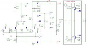
Virtually Earth
What is virtual earth. Simply put that with a single supply rail one uses the negative (or positive) as the common input/output terminal. Both supply rails carry ripple and noise, thus you have hum and noise on the common node.
A virtual earth turns a single supply into a dual supply with its center point, the summing point and this point is free from all common mode noises, in other words that which appears on both power lines.
It simply consists of two series caps between rails shunted by two resistors, or if you want the dc impedance to be low, two transistors. Thus you have a low impedance ground for both ac and dc paths sitting at V/2.
No your design can follow a typical split supply design making biasing and in/output coupling simple in that the junction of the two capacitors is the floating ground.
In headphone mania, many enthusiasts use another amplifier as the common, but the simple virtual earth achieves basically the same but with a lot less components.
With the circuit attached all grounds are connected to the earth point. There is no need for a series decoupling capacitor for the headphones and the front bias can go back to a single 15K resistor.
There is also no need for a headphone protection or mute as the caps are in series and will charge at the same rate thus maintaining V/2 from the outset.
Attachments
Last edited:
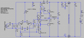
Hi Sheldon,
With virtual earth the schematic will resemble this.
Not sure why you addressed this to me Nico, but I like it.
Sheldon
Member
Joined 2009
Paid Member
Member
Joined 2009
Paid Member
Ok so you're saying that the impedance of the capacitors will be much lower than the Re of the transistors. I guess it means we didn't lose the output capacitor afterall, we just moved it to the other side of the load.
And the idea here is that the split supply rails topology has higher psrr which takes a lot of the burden off other elements of the design for keeping hum below the noise level of the output ?
And the idea here is that the split supply rails topology has higher psrr which takes a lot of the burden off other elements of the design for keeping hum below the noise level of the output ?
Hello
I often used a virtual ground for batteries powered preamps or other small power audio. I haved made for a friend a phono preamp using a single supply transfo and a virtual ground, it was two 1000 uF cap bypassing two zener in serial, it was dead quiet, no hum no noise.
You can use a single supply transfo and still have the advantage of the double rail circuit.
A page with few types of virtual ground circuits;
http://tangentsoft.net/elec/vgrounds.html
I vote for virtual ground.
Bye
Gaetan
Last edited:
I cannot figure out that there has been 11 223 views and only 400 odd posts. Were are the rest of you hiding?
Sometimes its better to watch
")
But Im a little confused about the power supply, why a single rail, is it a cost thing?
Would there not be an audible difference?
- Home
- More Vendors...
- AKSA
- Aspen Headphone Amp