Mihai's experience echoes. Low constant impedance = superbly controlled signal, thight accurate bass, extremely clean and articulated mid, precise treble, no SHHH instead of SSS. I don't know how else to describe it. Only downfall is it runs hot. It is the equivalent of class A in a power suply.
Only downfall is it runs hot. It is the equivalent of class A in a power suply.
Well, for sure it will throw off more heat than an unregulated supply. According to Mihai, the series current source should have about 5V to work with. For the FC100, the supply shunts about 10mA. That's with a class A amp running at 30mA, for 40mA total for the current source. So can maybe get by with around 10mA more than maximum draw for the HP amp. Not sure how much this HP amp runs into B. But still, maybe less heat heat from the supply than from the amp section?
Sheldon
Last edited:
It totally boggles my mind why you guys are talking about something "running hot" and in the same time we're talking about less than 50mA. Is this amp meant to run on batteries? I mean, your VCR blinking lights and the oven clock are beating your class A psu when it comes to current consumption.
I see no point in agonizing over a few milliamps. Ask yourself if you want good sound or average run of the mill sound. If you want the latter, batteries will do. So will a cap multiplier, and in fact any CRC filter will do. And why even bother with an all discrete HP? If you want average sound, you can get it from an opamp.
Sorry if I sound like ranting, but it's a bit frustrating seeing the project drifting all over the place. Perhaps the problem is that no one put down the specifications which this amp and psu should target.
It's your project and by all means go in the direction you want, but I would encourage you to go for something that's above average, not below.
Last edited:
Only downfall is it runs hot. It is the equivalent of class A in a power suply.
Well, for sure it will throw off more heat than an unregulated supply. According to Mihai, the series current source should have about 5V to work with. I'm not sure how much current the shunt element needs at it's minimum. But maybe only 10-20mA. Sims would tell the tail, I guess. So maybe less heat heat from the supply than from the amp section?
Sheldon
Member
Joined 2009
Paid Member
From Keantoken's simulation we find that 0.25A of signal swing puts about 100mV of audio onto the supply rail. If we want less than 100uV of that to appear at the output then we need a psrr of 1000:1. This is quite readily achieved with the RC filters already incorporated into the design if we pick the right R and Cs. From this perspective, a full blown shunt regulator isn't needed.
On the other hand, I really have no experience with headphone amps.
On the other hand, I really have no experience with headphone amps.
Member
Joined 2009
Paid Member

Member
Joined 2009
Paid Member
Sorry if I sound like ranting, but it's a bit frustrating seeing the project drifting all over the place. Perhaps the problem is that no one put down the specifications which this amp and psu should target.
There's a Russian joke along the lines 'what is the difference between a horse and a camel' ?
The camel was designed by a comittee...
I agree, we need specifications. But there's some debate as to how to map these specifications onto the subjective experience of people who have listened to various options.
PSU:
Nico has dealt nicely with the hum & noise specification - if you can't hear it on the power rail then you sure won't hear it at the output.
The remaining issue is load induced rail voltage sag and it's impact on the sound. Above, I threw out a target of 100uV at the output which looks possible without a complex regulator.
AMP:
It should be based on the 'AKSA' sound, remain simple and suitable for DIY'ers. This fixes the topology already.
Hugh also wants to keep it 'simple'. It's hard to do that at times. We could look at equalisation and worry about ear canal resonances - but that's another layer.
Last edited:
Member
Joined 2009
Paid Member
Ok, good luck to you guys. I've tried and failed.

Can you not propose some specifications as you suggest ?
Iko,
I'm baaaack....... from my six hour drive across the western plains. Look out!
Committees are a fact of life, and we have one of sorts here. It could be worse - it could be a business meeting! I could crunch the direction, but I won't. I want a bit of group ownership. Instead I will deliver a power supply which should keep everyone happy, and I will talk it over with KT, Nico, Bigun, and John privately and we will deliver something so bloody good your jaws will drop the ground......
Patience, gentleman. This is not a trivial problem, and details take time, and power supplies are REAL important.
Cheers,
Hugh
Hello.
1:
This is supposed to sound great, so we have little choice than to spend some money and deplete some ozone.
I think a large flaw in our design until now is that we're super-frugal. It is now becoming painfully apparent that this isn't what everyone wants. They are willing to pay for it if we guarantee it's success (so we should not be conservative).
EDIT: This post's old contents are obsolete in light of Hugh's post, so I deleted much of it.
- keantoken
1:
aim for above average, not below
This is supposed to sound great, so we have little choice than to spend some money and deplete some ozone.
I think a large flaw in our design until now is that we're super-frugal. It is now becoming painfully apparent that this isn't what everyone wants. They are willing to pay for it if we guarantee it's success (so we should not be conservative).
EDIT: This post's old contents are obsolete in light of Hugh's post, so I deleted much of it.
- keantoken
Last edited:
Here's one from Mihai (Roender): http://www.diyaudio.com/forums/showthread.php?p=1349112
Common parts, easily adapted for different voltage/current, single rail. Based on my experience with his amp, I bet it's a good design.
Layout for dual rail version: http://www.diyaudio.com/forums/showthread.php?p=1349246
BOM for dual rail version, @ 39V: http://www.diyaudio.com/forums/showthread.php?p=1354022
In this case association with a good amp does not make it a good design. Line regulation is about average, and load regulations is dismal. Perhaps he refined his design because as it is, it has rather poor performance.
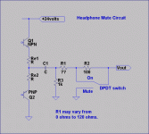
Mute circuit
Hugh & committee,
I think a headphone amplifier should have a mute circuit which can be used during power on, or plugging in or removing the headphones. Attached is a suggested circuit (copied from a 1970's Crown preamp).
Some headphones are designed to have a series resistor in the output. Some standard that I cannot recall specifies 120 ohms, but most headphone amp circuits that I have looked at use a lot less, typically 33 ohms. I suggest you provide one on the PCB as an option.
Also I have looked at the requirements for headphones, and the maximum voltage required for maximum output level is never more than 7 volts peak. There is a table on the Headwise website that lists max power levels and impedance, from this the maximum voltage can be calculated. The headphone with the highest requirement is the Sennheiser HD550 at just over 7 volts peak. The amplifier rail voltage therefore would need to be at least 18 volts (and 24 would probably be better).
I have a half built headphone amp that I abandoned about 10 years ago, I might use this circuit to finish it.
Paul Bysouth, October 2009
Attachments
In this case association with a good amp does not make it a good design. Line regulation is about average, and load regulations is dismal. Perhaps he refined his design because as it is, it has rather poor performance.
It may well be that this one is not appropriate for this amp, as it was designed for a class A input stage. It sure works fine for that. Terms like "dismal" and "poor" are not very useful in this context. I'm not concerned about the pejorative, but the quantitative. How good does it have to be to sound good for a particular application? What is required, and how close does a particular design come to meeting that quantitative requirement? That, of course, balanced against cost and complexity.
Sheldon
I don't know how good it has to be to sound good, because sound good is defined by everyone as per their own liking. I did not post the psrr plot, output impedance plot, and step response because when I did post zout for the design I contributed here there was absolutely no comment
I inferred that people probably don't care. Seeing that people were responsive to Nico's non-quantitative remarks, I followed suite and posted my impression. Do you think that's fair? If there's interest in comparing Mihai's regulator with the cap multiplier we can simulate it and post the results. I did, hence my comments. Of course, simulation is not reality, that's something we should keep in mind, but it's very useful to prune the lesser solutions.
Do you think that's fair?
I'm interested only in the technical discussion. I brought up Mihai's reg. because it's simple and inexpensive to execute, and I've had good experience with his amp. You pointed out that it was not among the best, in relative terms, and that it may not be good for this application. OK, fine. But unless that's expressed in a quantitative fashion, then it's not very helpful.
Fair? I responded because your reply spoke directly to my original post. I'd like to see others move things along a quantitative path too, but I'm not here to referee.
On a side note, and as an open question to all; Since we have the amp, shouldn't the sims be done with the whole package, rather than each section in isolation? Wouldn't that address the quantitative requirements better?
Sheldon
I should add, that I'm far, far from expert here.
Last edited:
Sheldon, my intention was only to help, not to discredit Mihai's circuit. Here are plots for Mihai's regulator next to some other, so we can compare. The step response is how the "regulated" voltage changes when the load steps alternately between 20mA and 25mA, with a period of 40uS. The voltage in has a AC component of 120Hz, 2V p-p (a little bit extreme).
The first row of is the psrr plot, which quantifies the amount of line regulation vs frequency. That is, if input to the regulator was a very unstable voltage (of various frequencies), how stable would the output voltage be. Flatter and lower curves are better. The dotted line is the phase.
The second row quantifies load regulation. That is, if the load draws current, can the regulator keep the output voltage steady? At different frequencies the regulator normally has different performance. It is very difficult to design and build regulators that have low output impedance at higher frequencies. There are people who think that the flatness of this plot (both phase and amplitude, dotted and solid lines) especially in the audio frequency range has paramount importance to the sound one gets.
The third row simulates a square wave load of very humble amplitude (20 to 25mA), coupled with an AC component of 2V p-p in the input. Here we'd like to see no ringing (the ability of the regulator so stabilize the voltage quickly), and as flat a line as possible.
Hopefully this explains my somewhat negative comments. It'd be hard for me to find other terms for describing these plots. I was also trying to avoid the time necessary to explain all this, and capture the plots, etc. I was hoping the more experienced people in the committee would just see what I mean.
PSRR
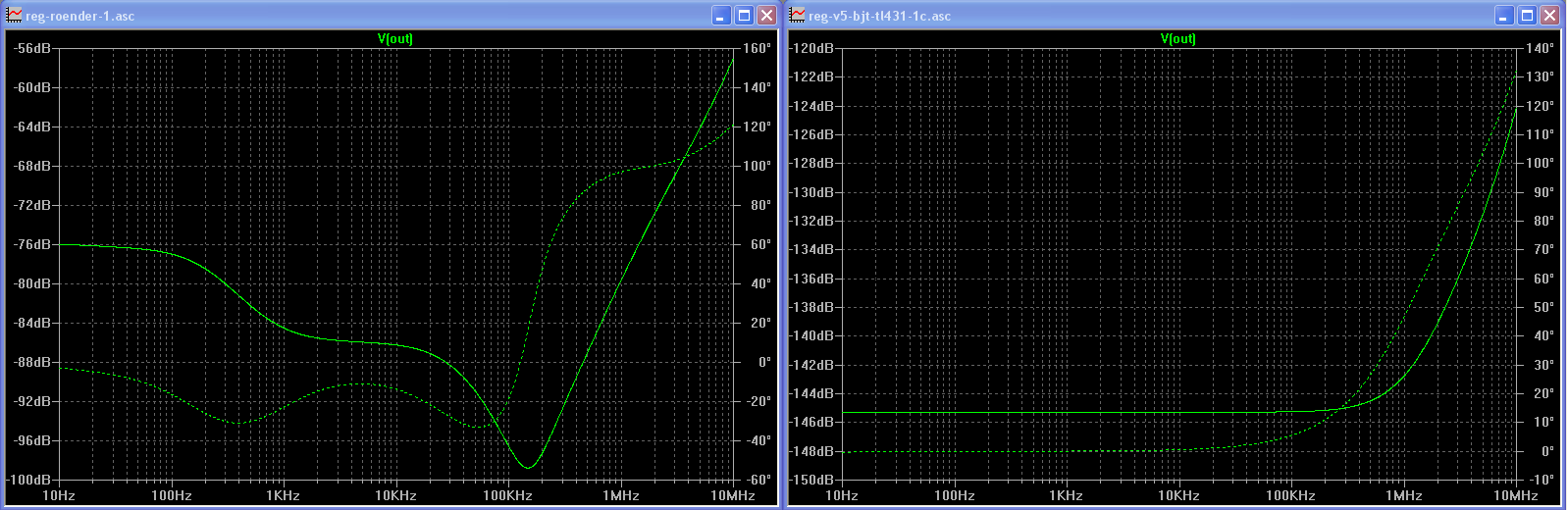
Output impedance
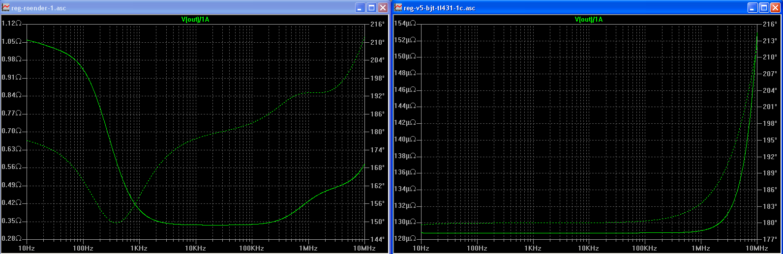
Step response
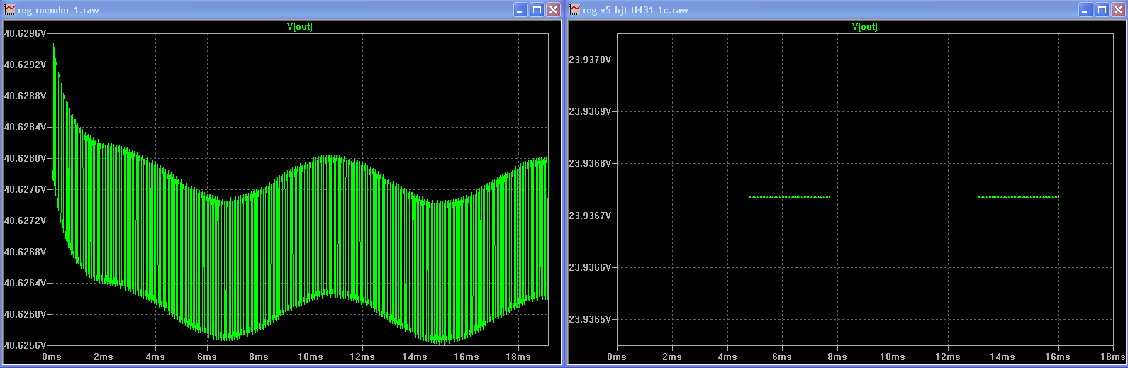
The first row of is the psrr plot, which quantifies the amount of line regulation vs frequency. That is, if input to the regulator was a very unstable voltage (of various frequencies), how stable would the output voltage be. Flatter and lower curves are better. The dotted line is the phase.
The second row quantifies load regulation. That is, if the load draws current, can the regulator keep the output voltage steady? At different frequencies the regulator normally has different performance. It is very difficult to design and build regulators that have low output impedance at higher frequencies. There are people who think that the flatness of this plot (both phase and amplitude, dotted and solid lines) especially in the audio frequency range has paramount importance to the sound one gets.
The third row simulates a square wave load of very humble amplitude (20 to 25mA), coupled with an AC component of 2V p-p in the input. Here we'd like to see no ringing (the ability of the regulator so stabilize the voltage quickly), and as flat a line as possible.
Hopefully this explains my somewhat negative comments. It'd be hard for me to find other terms for describing these plots. I was also trying to avoid the time necessary to explain all this, and capture the plots, etc. I was hoping the more experienced people in the committee would just see what I mean.
PSRR
Output impedance
Step response
Iko,
I'm baaaack....... from my six hour drive across the western plains. Look out!
What, you didn't ride?
Committees are a fact of life, and we have one of sorts here. It could be worse - it could be a business meeting! I could crunch the direction, but I won't. I want a bit of group ownership. Instead I will deliver a power supply which should keep everyone happy, and I will talk it over with KT, Nico, Bigun, and John privately and we will deliver something so bloody good your jaws will drop the ground......
Patience, gentleman. This is not a trivial problem, and details take time, and power supplies are REAL important.
Cheers,
Hugh
Great, looking forward to it!


Hopefully this explains my somewhat negative comments. It'd be hard for me to find other terms for describing these plots. I was also trying to avoid the time necessary to explain all this, and capture the plots, etc. I was hoping the more experienced people in the committee would just see what I mean.
[/IMG]
Thanks Ikoflexer. I really wasn't asking for that much detail (though it doesn't hurt) - just some indication of how far from a target value it might be. And for that, I don't mind some subjectivity based on experience either. For instance, "I think the regulator for this supply should have at least two times better load regulation (or whatever), or it may be audible". If the reg. you posted is no more complicated or expensive, then I see no reason not to prefer it - that wasn't my objection. I don't have a dog in this hunt, just want to know the reasoning.
Sheldon
- Home
- More Vendors...
- AKSA
- Aspen Headphone Amp