Hugh also sent me the file.
One thing I might be wary of is C4. The TL431 is essentially an amplifier, and all amplifiers need some sort of stability compensation. I used such a capacitor in a schematic once and was told to delete it because it would inject noise into the output (not to mention all capacitors have some ESL).
To be safe, I might put a 10 ohm or even 100 ohm resistor in series with C4, which would keep the TL431 more within it own BW limits, making stability compensation more effective. I don't think this would have a large effect on performance. This is purely theoretical and untested, just a brainfart by me perhaps, and I doubt it is necessary.
I am content with Hugh's schematic.
I am not sure how much DC contamination can be expected on an AC line, but such a capacitor might be expensive as it would have to be non-polar.
Bigun, your attachment is blank.
- keantoken
Last edited:
Update.
Hugh said in his Email that a Darlington would be a good change (though I personally don't know that it is necessary, and it would potentially increase output impedance).
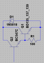
So here it is: Reverse bias diode for protection, 100 ohm bias resistor to keep the master transistor well within its current range.
- keantoken
Hugh said in his Email that a Darlington would be a good change (though I personally don't know that it is necessary, and it would potentially increase output impedance).
So here it is: Reverse bias diode for protection, 100 ohm bias resistor to keep the master transistor well within its current range.
- keantoken
Attachments
I am not sure how much DC contamination can be expected on an AC line, but such a capacitor might be expensive as it would have to be non-polar.
I would need to be mains rated X or Y also.
I will point out something else:
The PSU as it is will have slow turn-on, except that the TL431's output will jump to 2.5V immediately at turn-on, until C4 charges up. I recommend that we delete C4 and instead use a separate capacitor entirely in parallel with the TL431. This way, the TL431 will only turn on when it reaches the nominal voltage, with no thumps. This way the TL431 will also have some form of local decoupling.
- keantoken
I would need to be mains rated X or Y also.
And what current would it have to pass? Would it have to be a large value in order to pass enough AC at 60Hz to power the circuit?
- keantoken
Member
Joined 2009
Paid Member
Hugh also sent me the file.
One thing I might be wary of is C4. The TL431 is essentially an amplifier, and all amplifiers need some sort of stability compensation. I used such a capacitor in a schematic once and was told to delete it because it would inject noise into the output (not to mention all capacitors have some ESL).
To be safe, I might put a 10 ohm or even 100 ohm resistor in series with C4, which would keep the TL431 more within it own BW limits, making stability compensation more effective. I don't think this would have a large effect on performance. This is purely theoretical and untested, just a brainfart by me perhaps, and I doubt it is necessary.
I am content with Hugh's schematic.
I am not sure how much DC contamination can be expected on an AC line, but such a capacitor might be expensive as it would have to be non-polar.
Bigun, your attachment is blank.
- keantoken
oops, which attachment is blank ?
My sims showed a rather quick turn-on too, followed by an under-damped movement to the final output voltage. I wasn't too confident on the device models I used but it didn't look good and ripple was above our target.
Stability - I'm trying to figure out if there is an issue. It's worth looking at the data sheet [http://focus.ti.com/lit/ds/symlink/tl431.pdf]. I think C4 was positioned where it is to provide a slower turn-on and using it on the reference input to the regulator potentially gives it more leverage over the output voltage = lower cap value. I'm not sure if affects stability, it couples the +ve input of the 'op-amp' to the equivalent of it's +ve supply rail ?
Hugh says he's tried this circuit with success and that's always a good sign.
HOWEVER....Putting C4 in parallel with the shunt regulator reverts the design to something that's closer to a simple Capacitance multiplier - which I'm much more comfortable with understanding the functionality of. And since he's away for a couple of days we can wreak some havoc

So short answer is yes - I agree, let's move C4 and put it across Z1.
I'm not convinced of the need for a Darlington pass device either.
Member
Joined 2009
Paid Member
And what current would it have to pass? Would it have to be a large value in order to pass enough AC at 60Hz to power the circuit?
- keantoken
Aren't we looking at less than 50mA at 120Vac to get 20Vac 250mA out the other side?
Member
Joined 2009
Paid Member
The more I look at the sims, the less I like it. Ripple is way too high. Oh dear.....
It's the CCS that I don't like. I have stripped it out, left in the LED as a power-on indicator. The voltage divider feeding the shunt regulator reference is fed via a simple resistor and C4 is put across Z1 so that we now have a classic Capacitance Multiplier.
Hugh - we are mutineering !
The simulations look simply wonderful. Turn-on is smooth and slow, the ripple is simply 'gone' !
here's the sim. file.
Attachments
It's the .asc file that's blank.
I'm not familiar with AC calculations, can someone else calculate the value for the mains cap? Or perhaps Nico knows of a suitable value? (I'm not sure why a mains cap would be necessary, this is the only place I've heard of DC contamination being a potential problem)
In Hugh's own words, "The capacitor multiplier effect is not strictly present", making the capacitor parallel would certainly change this. It would actually help if the cap's ESR was smaller than the TL431's (but I don't know if this is true. We could calculate the 431 ESR from the datasheet).
Say we used a 100uF cap. at 13mA, how long would it take to charge up?
- keantoken
The more I look at the sims, the less I like it. Ripple is way too high. Oh dear.....
It's the CCS that I don't like. I have stripped it out, left in the LED as a power-on indicator. The voltage divider feeding the shunt regulator reference is fed via a simple resistor and C4 is put across Z1 so that we now have a classic Capacitance Multiplier.
Hugh - we are mutineering !
The simulations look simply wonderful. Turn-on is smooth and slow, the ripple is simply 'gone' !
here's the sim. file.
Taking out the CCS doesn't make much sense to me... What exactly is wrong with it? The CCS very effectively isolates the output from line ripple. Perhaps we're being too purist here...
We could at least use a Jfet CCS. The CCS cuts down loading on the 431, which already has to contend with the transistor's base current.
EDIT: okay, I've looked at the sim, and the TL431 is just dead... totally nonresponsive... I don't think it's working!!! We should get the model working before we do anything else...
- keantoken
Keantoken - I like the optional bootstrap take-off point. Have you looked at the impact on FFT harmonics over a range of frequencies and signal levels - does it 'hold up' ?
THD is smaller by about .002% the last time I checked. I also checked in AB mode. Distortion is still improved when it goes into AB. I haven't yet seen a negative affect on performance.
- keantoken
EDIT: okay, I've looked at the sim, and the TL431 is just dead... totally nonresponsive... I don't think it's working!!! We should get the model working before we do anything else...
- keantoken
Okay. I'm not sure if it was necessary but I put together a model that should work reasonably well for the TL431. ESL was guessed, dynamic impedance is based on the datasheet which says .15 ohms (ESL is determined by the G-source's gain).
Let's look at this. It takes .5 seconds to warm up, so I think we're a go here.
I was too lazy to even look at the model included in the schematic... (and my grandma always say'd, "lazy people work three times harder!")
I also added reasonable values for ESR to the multiplier cap, so we're not too optimistic.
- keantoken
Attachments
Last edited:
I suggest you double all these time estimates. taking you to about 18th October.makingI suggest you allow a time frame for both activities, say 3 days for the schematic and another 3 days for the PCB general layout.
This will take us to about Thursday next week.
On 19th October I will start the PCB layout
Last edited:
Knocked the regulator together and gave it the headphone test with 100 ohm load connected across the output. It is very quiet and no power supply hum is audible, but regulation is poor.
The output drops by 470mV when switching to 100 Ohm load and 700 mV when switching to 50 Ohm load. An error correction amplifier could improve matters but complicates the circuit considerably.
An LM317 may still be a better and simpler opion.
Nico
The output drops by 470mV when switching to 100 Ohm load and 700 mV when switching to 50 Ohm load. An error correction amplifier could improve matters but complicates the circuit considerably.
An LM317 may still be a better and simpler opion.
Nico
Member
Joined 2009
Paid Member
Knocked the regulator together and gave it the headphone test with 100 ohm load connected across the output. It is very quiet and no power supply hum is audible, but regulation is poor.
The output drops by 470mV when switching to 100 Ohm load and 700 mV when switching to 50 Ohm load. An error correction amplifier could improve matters but complicates the circuit considerably.
An LM317 may still be a better and simpler opion.
Nico
Nico,
You are a champion ! - it's great that you've tried the regulator.
Personally, I'm not worried about voltage regulation per se, if it's quiet then we accomplished the task. Unless I'm missing something, small changes in the supply rail voltage aren't a big problem - am I missing something, should I be wanting a constant voltage ???
Of course it means it's working more like a capacitance multiplier than a regulator. A cap multiplier doesn't regulate the voltage, it's function is to reduce psu ripple and to isolate channels from each other.
It would be interesting to know how it performs by your listening test if you take the shunt regulator away - just a plan cap multiplier ?
Keantoken - your new model looks great, I'm going to transfer the file to my laptop to try it out....
Member
Joined 2009
Paid Member
Taking out the CCS doesn't make much sense to me... What exactly is wrong with it?
Not really any technical reason, but that it adds some complexity where I'm not sure that it's needed. I see that it helps establish a current flow through a potential divider for the Z1 reference signal but I wasn't sure this was needed.
The other thing is, I'm still looking at this circuit as if it were an 'enhanced' cap multiplier in which a simple zener is replaced by the TL431. In this case a simple resistor works fine.
The reason I don't view this circuit as a voltage regulator is perhaps a bit over-simplified: If the TL431 maintains a constant voltage at the base of the pass transistor then the voltage at the emitter will depend on the current flow through the transistor. Besides, I can't see how it can keep a constant voltage because there is no feedback mechanism to tell the 'regulator' what is at it's output.
p.s. Sometimes I find that I learn more about a circuit under simulation by taking bits out and putting bits in.
Last edited:
Member
Joined 2009
Paid Member
Keantoken,
I ran your simulation (strange, but the inductors were all out of position, some incompatibility between our versions of Spice ?). Your model was nicely done. I like how you added a sinusoidal load, very neat.
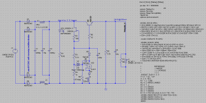
I added 3 duplicates of the circuit to my simulation file. The original one I labeled vsupply_K (after you !), the next one as vsupply_G (after me) which replaces the CCS with a simple resistor, then vsupply_Z which replaces the shunt regulator with two simple 12V zener diodes in series and finally vsupply_C which removes the zener diodes for the simplest possible cap multiplier.
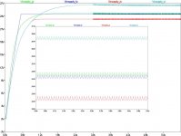
The attached plot shows the results. With a CCS (dark blue trace) the rate of flow of charge onto C4 is constant so the voltage ramps up close to linear (as expected). All the other traces ramp up without a CCS so the rate of flow of charge onto C4 depends on the voltage on C4 and is therefore exponential (as expected).
The cut-out in the centre of the attached plot is an enlargement of the supply rail voltages near the end of the simulation when the sinusoidal loads are active.
The basic cap multiplier puts in a good show.
I ran your simulation (strange, but the inductors were all out of position, some incompatibility between our versions of Spice ?). Your model was nicely done. I like how you added a sinusoidal load, very neat.
I added 3 duplicates of the circuit to my simulation file. The original one I labeled vsupply_K (after you !), the next one as vsupply_G (after me) which replaces the CCS with a simple resistor, then vsupply_Z which replaces the shunt regulator with two simple 12V zener diodes in series and finally vsupply_C which removes the zener diodes for the simplest possible cap multiplier.
The attached plot shows the results. With a CCS (dark blue trace) the rate of flow of charge onto C4 is constant so the voltage ramps up close to linear (as expected). All the other traces ramp up without a CCS so the rate of flow of charge onto C4 depends on the voltage on C4 and is therefore exponential (as expected).
The cut-out in the centre of the attached plot is an enlargement of the supply rail voltages near the end of the simulation when the sinusoidal loads are active.
The basic cap multiplier puts in a good show.
Attachments
Bigun, load regulation will be the same in any case unless we do one of two things, or both:
1: Put the 431 voltage divider at the output, introducing global NFB.
2: Use a CFP pass transistor configuration.
So what we're worrying about right now is line regulation.
I've got this huge post I'm about to post, so be ready...
- keantoken
1: Put the 431 voltage divider at the output, introducing global NFB.
2: Use a CFP pass transistor configuration.
So what we're worrying about right now is line regulation.
I've got this huge post I'm about to post, so be ready...
- keantoken
- Home
- More Vendors...
- AKSA
- Aspen Headphone Amp