Member
Joined 2009
Paid Member
TL431 shunt regulator
I shalln't argue with the Master.
but... this means we have an Opamp in our camp, hiding as it may within the psu
I agree with Nico about the capacitance multiplier ramping the voltage. I had not thought of this. It should also not pop when you plug in the headphones, as too many do.
I also like the idea of using zero NFB buffers instead of opamps for the crossfeed.
I am starting to think someone really should ginnea pig all these ideas...
- keantoken
I also like the idea of using zero NFB buffers instead of opamps for the crossfeed.
I am starting to think someone really should ginnea pig all these ideas...
- keantoken
Gareth,
The TL431 is a remarkable device. Even John Broskie uses them, and they are used in the Supratek preamp power supply (I know because I had a hand in it).
In any event, they don't pass signal, and they have a largish cap across them, which should be configurable to give soft turn on, a desireable quality.
Trialling each and every one of these ideas would take hundreds of hours. I have in fact done many of them already, and Nico has vindicated my choice of the amp topology. What will take the time now is the crossfeed and the power supply. I guess that's why design is tricky..... lots of man hours. Volunteers anyone?
Hugh
Last edited:
I am starting to think someone really should ginnea pig all these ideas...
- keantoken
I have a lot going on, but I may find time over the weekend to cobble it together. I have all the parts.
Now, listening...is another story. To me, most amps sound the same, if they are working properly. If there are Earth moving, subtle differences from one component choice to another, it is beyond my capacity to resolve.
Add to that is my hearing is on a steady downward trajectory ...

Hugh,
are you going to supply a complete kit of parts or only the PCB? Reason is why I am asking is that laying the PCB one must have a clue of the components the guys will want to use, for example headphone socket foot prints are not the same, nor are potentio meters. Capacitor pitch may differ, etc.
Supplying the kit would make sense and the PCB design would be much easier. Besides the amps will be consistent.
Who will draw the final schematic and select the components?
I do not have any project on the go, as I mentioned, I built my last amp and if you want a hand at PCB layout, it will be only with pleasure.
Nico
Hi Nico,
No, this is an open design, and while I know different components have different footprints, and pleasing all comers is difficult, it's already starting to dominate my time and I won't be making a penny from it..... and right now I'm under the pump with orders, so development time is tricky. Hell, I'm simulating the power supply right now!!
Hugh
Hi Gareth,
Since you are the appointed "Project Manager" could you start finalising the schematic - draw one from every ones wishlist as it appeared here, let the guys comment on what the final design will look like and then freeze it - NO FURTHER CHANGES. Don't allow the guys to just demand I want, they must show the schematic of what they want so others can agree or disagree with it.
You then need to suggest a bill of components that would most suit everyone, most important is outline drawings of the selected components, especially pots and large caps or esoteric stuff that is not common then post it here or forward it to me (nico_ras@telkomsa.net)
Next step would be to throw open a general PCB layout. i.e. where you want everything placed, volume control, input connector, headphone connector, etc.
Post your suggestion and again let every one have his/her say about it. Once you are satisfied then - FREEZE THE DESIGN no further changes.
I suggest you allow a time frame for both activities, say 3 days for the schematic and another 3 days for the PCB general layout.
This will take us to about Thursday next week. On Friday I will start the PCB layout and when finished I will e-mail it to Hugh for comments and when we agree it is workable it will be posted on the forum for final view and then it is up to you to apoint whomever will have the PCB made and arrange your group buy, etc.
Hugh if I missed something please shout out loud. Mind you anybody can have a say.
Have fun at it.
Kind regards
Nico
subtle differences from one component choice to another, it is beyond my capacity to resolve.
Add to that is my hearing is on a steady downward trajectory ...
Hi John,
I think the point here is to listen that there is no obvious flaw. I don't think any of us are capable of hearing something earthmoving without being able to compare it to something less earthmoving.
You are experienced in both designing and listening to spot a flaw in the sonic representation of the system and honest enough to give your real opinion, regardless whether it is good or bad.
Kindest regards
Nico
...and honest enough to give your real opinion, regardless whether it is good or bad.
This is true...
I might candy coat it a bit but it can still be a bitter pill. 
I'm not going to have time this weekend - too many things going on, but looking at the design, having simulated it, I doubt there will be a problem. It's simple and basically bulletproof. There may be some compensation issues, but that is best left till the board is finalized to tweak.
Offset on a headphone amp can be bad as it requires only a small offset to push or pull the cones off rest. Headphones do not have a high excursion and I would consider replacing the emitter degeneration resistors with an equivalent value 25 turn trimpot to finely adjust the offset to zero.
Kind regards
Nico
John,
one candy coats ones own designs but normally slate anothers design, is this not the way of DIY audio, now why would you want to change that culture???

Kind regards
Nico
John,
one candy coats ones own designs but normally slate anothers design, is this not the way of DIY audio, now why would you want to change that culture???
I'm going away for three days, back Tuesday. Gareth, please advance this as you see fit!
Nico, John, OS, thanks very much for the input. I'm committed to 24V single rail operation, using a voltage divider and cap decouper to set input bias around 12V and a shunt regulated power supply with CMC to remove ripple. (Here's John's good find: http://search.digikey.com/scripts/DkSearch/dksus.dll?Detail&name=PLK1156-ND)
The cross feed should be done with a simple double ganged linear pot at the two inputs, with a switch - perhaps a pull action in the same pots - incorporated to remove mixing. This will vary with source impedance, but once attached to a particular source would remain consistent and predictable. I think CF should have an LED indicating it is activated.
I will doodle on used envelopes whilst away but am confident it's getting close to component selection and layout.
Thanks to all who continue to contribute. Design by committee is always slow and tedious but with focus the results are always good.
Cheers,
Hugh
Offset on a headphone amp can be bad as it requires only a small offset to push or pull the cones off rest. Headphones do not have a high excursion and I would consider replacing the emitter degeneration resistors with an equivalent value 25 turn trimpot to finely adjust the offset to zero.
You can get a 25 ohm rheostat from radioshack I believe, but because it is wirewound it is somewhat inductive. I think that a better option is putting a pot on the emitter leg of the LTP.
- keantoken
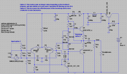
Okay, here it is...
I really feel like I'm forgetting some options...
I think the modified bootstrap is agreed upon, but if anyone has any objections say them now or forever hold your peace... If you want my reasons for the mod, look at ratio of Ic(Q3) to I(R6) with and without the modified bootstrap (you will see that the VAS works much harder without the mod).
The input option would enable us to filter out dangerous RF by placing a small cap across R11. It would also allow us to have an integer value of gain, say exactly 10 if we used a network of 10k over 1k ("yeah, but what is the gain?" "it is, uh... 7.648, I think"). For this to work, R17 must = R10 and R11 must = R9.
I didn't include the crossfeed for lack of schematic.
- keantoken
Attachments
I want to draw attention to the schottky idea...
Please look at this schematic. Even on transients no transistor turns off, preventing crossover tranients.
It could be modified by putting resistors across the schottkys, or by putting a resistor between the OP emitters.
- keantoken
Please look at this schematic. Even on transients no transistor turns off, preventing crossover tranients.
It could be modified by putting resistors across the schottkys, or by putting a resistor between the OP emitters.
- keantoken
Attachments
Member
Joined 2009
Paid Member
OK, I have received from Hugh his favoured design for the PSU.
Nico has suggested a dc blocking cap on the transformer primary to remove local dc contamination of the AC mains. And also suggests adding a protection diode across Q1 in case it's inadvertently reversed biassed by wandering screwdrivers etc. during 'testing' ... sounds like a good option to me.
Hugh recommends the BYC26E soft-recovery diodes for the rectifier (or UF4001) - I've previously used the BYW 29E units which are equivalent singulated diodes.
The shunt regulator, Z1, should be a TO126 (or better) version with a small heatsink to source the base current required for Q1. The power-on rate is controlled by the current flow into C4.
The 'last capacitor', C5, will flow the bulk of the a.c. signal and should be of high quality (Hugh recommends EXR Hitano, with film bypass if so desired).
I've coded the design into Spice - files attached. I'm not that happy with the results which I feel are not representative of the circuit performance, being constrained by poor device models (embedded into the files). So feel free to improve on the sims.
No doubt this is a much higher performance psu than the simple capacitance multiplier I started with - gotta love how things evolve beyond what you thought was possible.
Keantoken - I like the optional bootstrap take-off point. Have you looked at the impact on FFT harmonics over a range of frequencies and signal levels - does it 'hold up' ?
Attachments
- Home
- More Vendors...
- AKSA
- Aspen Headphone Amp