Until papaZBill can help...
Check the signal on the output inductors before the relay. You'll likely see a lot of DC offset as the amp tries to power up.
If so, check the 12v Zeners that are in the driver section. Many times they go leaky and they won't provide the 12v for the drive circuit.
Check the signal on the output inductors before the relay. You'll likely see a lot of DC offset as the amp tries to power up.
If so, check the 12v Zeners that are in the driver section. Many times they go leaky and they won't provide the 12v for the drive circuit.

I don't have the drivers,can I used the C2690A/A1220A
https://www.fairchildsemi.com/datasheets/KS/KSC2690A.pdf
HTTP 301 This page has been moved
https://www.fairchildsemi.com/datasheets/KS/KSC2690A.pdf
HTTP 301 This page has been moved
I don’t have any experience with using these devices in this particular application. I believe these devices are more suitable for linear applications, such as Class A/B drivers, not as Class D driver.
Perry or someone else may be able to recommend a better replacement or confirm if they are a good replacement
Perry or someone else may be able to recommend a better replacement or confirm if they are a good replacement
Last edited:
I can't say that I've used these in this amp but if they don't run hotter than the originals in the other drive circuit, I'd expect them to be OK.
The current rating is higher but they may not perform as well at the switching frequency of the output stage.
When burning the amp in, also make sure that both sets of output transistors operate at about the same temperature. If one side runs hotter, it could be because the drive circuit isn't producing a clean drive signal.
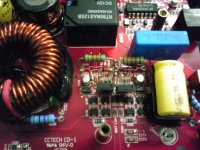
Virtually all of the amps that use this class D circuit have unequal N and P-channel FETs. You can see the grouping by the connections to the rails. The two N-channels have their source legs on the negative rail. The three P-channel have their source legs on the positive rail. You can see the basic circuit by downloading the JBL BP1200.1 service manual which is available at various sites online (or in the JBL folder if you have the tutorial).
If your are seeing full rail voltages(approx. +/-71 volts) on the outside legs of all outputs. (Bank of 2 IRF640's and bank of 3 IRF9640's on either side) the amp is not oscillating.
Check the DC voltages around the LM361 and look at the signal on Pins 4,11 and post.
If you haven't done so, check the +/- 12v regulator voltages. You can check them off the Preamp board header pins. If I'm not mistaken this is a older version and you should have five pins on the preamp board, newer version will have 9 pins. Check all pins and post.
- Status
- This old topic is closed. If you want to reopen this topic, contact a moderator using the "Report Post" button.
- Home
- General Interest
- Car Audio
- zx750.1 kicker