simple question, would a couple zeners survive being placed in a NFB loop of a power amp, back-to-back, each one chosen at half the total voltage so clipping takes on the zener curve instead of saturated transistors? i'm new to power amps and the higher voltage and current restrictions, i've already burned a couple output transistors during my fumblings.
It doesn't sound a very good method tbh, in fact I can't see how it could work. It would help if you drew what you have in mind though.
If you're destroying output devices then I think something other than a bit of clipping is going on. Use a bulb tester on your power supply to limit current and damage.
If your stuck on a particular design then post a diagram and we'll see if anything obvious stands out.
If you're destroying output devices then I think something other than a bit of clipping is going on. Use a bulb tester on your power supply to limit current and damage.
If your stuck on a particular design then post a diagram and we'll see if anything obvious stands out.
They would survive, but the technique isn't very good: zeners will introduce horrendous non-linearities well before the threshold, and even far of the threshold the non-linear capacitance will introduce distortion.simple question, would a couple zeners survive being placed in a NFB loop of a power amp, back-to-back, each one chosen at half the total voltage so clipping takes on the zener curve instead of saturated transistors?
In addition, they need to be precisely adapted to the supply voltage, and if the mains fluctuates, the threshold will not adapt itself.
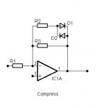
A smarter way is to use a diode gate: that way, the clipping threshold will track the supply voltage automatically, and reverse-biased diodes will create much less non-linearities.
Here is an example of such a circuit (with an opamp playing the role of the PA): normally, the diodes are kept reverse-biased by the resistive dividers, but because the members are slightly unequal, they will make the diodes conduct when the output voltage comes too close to the supply rails.
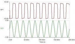
The clipping is "soft" because of the internal resistance of the dividers: the degree of softness can be adjusted by the ratio of R1 -> R4 to R5. In an actual amplifier, you will have a great freedom of choice for the values.
If you don't want any softness, you can bypass the resistors (and correct their value): it's the second example
Attachments
i burned a 3904 and 3906 pair using them far beyond their limits. foolish mistake, but i hope i learned from it. i'm playing with 3055's and 2955's now and they are working excellent, until i overdrive them of course.
i intend to use this method in a power amp that's meant to distort, i would want full output swing of course so it sounds like i'd have to go with a slightly higher voltage zener.
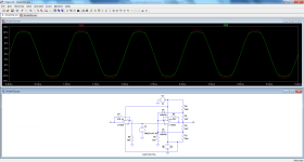
the first image is the basic idea, of course lacking some details and not final.
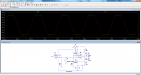
second is without the diodes, third is with them. the simulation i used was actually using only 24v and the zeners used were 17v instead of 12v. the 12v zeners did make the output swing less by about 2 volts so i kept upping the value by 1v until it matched up nice. i assume real life results would be different, but since i don't think i'll mind the distortion, it sounds like this will work?
i intend to use this method in a power amp that's meant to distort, i would want full output swing of course so it sounds like i'd have to go with a slightly higher voltage zener.
the first image is the basic idea, of course lacking some details and not final.
second is without the diodes, third is with them. the simulation i used was actually using only 24v and the zeners used were 17v instead of 12v. the 12v zeners did make the output swing less by about 2 volts so i kept upping the value by 1v until it matched up nice. i assume real life results would be different, but since i don't think i'll mind the distortion, it sounds like this will work?
Attachments


I did it in a guitar amp and it works")
aw, darn it. i guess i should have known i wasn't the first. i'll never be the prettiest now...
- Status
- This old topic is closed. If you want to reopen this topic, contact a moderator using the "Report Post" button.
- Home
- Amplifiers
- Solid State
- Zener diodes in feedback loop of power amp