I need help in troubleshooting my yamaha cdx-1100.
The issue is that it can only occasionally read TOC. It only does that when spinning the disk fast and clockwise.
Most of the time cd-player struggles to spin the disk and after a very short time it starts to spin counter-clockwise.
Here is the movie showing the ploblem
https://www.dropbox.com/sc/8e46qwdsbc77ydw/AAC7VoY6sVt9mWU8fdpq79Mra
CD players has a DC brushed motor which is controlled by a photodiode and receiver located under disk platter. If I disconnect three wires (FG,LED,5D) from the main digital PCB, rotation speed of spindle motor increases slightly and CD reads TOC 70% of the time. The same time it won't stop the rotation of the disk when opening a tray.

I have checked:
- RF pattern
- Focus
- all voltages on ICs, OP-AMPs
- bad joints and wire connections
- some of the caps with ESR meter
Everything seems to be fine.
Any ideas?
Thanks
The issue is that it can only occasionally read TOC. It only does that when spinning the disk fast and clockwise.
Most of the time cd-player struggles to spin the disk and after a very short time it starts to spin counter-clockwise.
Here is the movie showing the ploblem
https://www.dropbox.com/sc/8e46qwdsbc77ydw/AAC7VoY6sVt9mWU8fdpq79Mra
CD players has a DC brushed motor which is controlled by a photodiode and receiver located under disk platter. If I disconnect three wires (FG,LED,5D) from the main digital PCB, rotation speed of spindle motor increases slightly and CD reads TOC 70% of the time. The same time it won't stop the rotation of the disk when opening a tray.
I have checked:
- RF pattern
- Focus
- all voltages on ICs, OP-AMPs
- bad joints and wire connections
- some of the caps with ESR meter
Everything seems to be fine.
Any ideas?
Thanks

Readout pin 15 IC805

When idle

I noticed that the problem with CD starts immediately after focus lock.
CD will spin normally as long as focus is not established.
I've checked again RF. It should read 2,5Vpp but it is variable

Does it mean the laser diode is dying?
I have replaced IC110, IC107,109, Q123, Q124. Problem remained.
When idle
I noticed that the problem with CD starts immediately after focus lock.
CD will spin normally as long as focus is not established.
I've checked again RF. It should read 2,5Vpp but it is variable
Does it mean the laser diode is dying?
I have replaced IC110, IC107,109, Q123, Q124. Problem remained.
Readout pin 15 IC805
View attachment 537481
When idle
View attachment 537482
I noticed that the problem with CD starts immediately after focus lock.
CD will spin normally as long as focus is not established.
I've checked again RF. It should read 2,5Vpp but it is variable
View attachment 537483
Does it mean the laser diode is dying?
I have replaced IC110, IC107,109, Q123, Q124. Problem remained.
The clock signal looks fine - however, I am not sure about the frequency value.... Anyway, I don't think this clock signal is a problem.
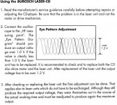
Try increasing the laser pick-up value by turning a tiny trim-pot (located on a laser itself), by 3-4 deg clockwise. That should get it going. See attached documentation.
Attachments

I downloaded the service manual. The clock signal at pin 28 doesn not look good at all. Check this signal at its source: YM3816, pin 34. It should be a stable 4.3218 MHz clock signal. I can e-mail the pdf service manual to you..... but something tells me you have it already.
I have a copy of service manual however it is not best quality. Some of the pages are difficult to read and there is no reference information.
I might be wrong but I think clock signal should be square wave.
The signal on pin 28 (clock output from YM3816) is not like that and very noisy.
Is this possible that variable amplitude of RF is due to some problem with HF amplifier Q101-104?
I might be wrong but I think clock signal should be square wave.
The signal on pin 28 (clock output from YM3816) is not like that and very noisy.
Is this possible that variable amplitude of RF is due to some problem with HF amplifier Q101-104?
I checked pin 34 of YM3816 and pin 28 of IC805. It seems the clock is generated only during play.
This is how it look:

I decided to wait and not to adjust laser yet. The pot is sealed.
I don't want to make problem worse.
I will start on weekend with proper adjustment of all FOF,EFB, FG etc, maybe replace IC111A (STA451C)..
Laser is very likely weak. When I knock to the case it immediately loses track. The same when trying to skip to the next song - cd starts to spin counterclockwise the same time I press the button.
This is how it look:
I decided to wait and not to adjust laser yet. The pot is sealed.
I don't want to make problem worse.
I will start on weekend with proper adjustment of all FOF,EFB, FG etc, maybe replace IC111A (STA451C)..
Laser is very likely weak. When I knock to the case it immediately loses track. The same when trying to skip to the next song - cd starts to spin counterclockwise the same time I press the button.
I use ElektroTanya | Service manuals and repair tips for electronics experts
You'll have to pass a little test in electronics to gain access to downloads; at least I had to, but that was probably some 5 - 6 years ago. Maybe they have different rules now.
Nick
You'll have to pass a little test in electronics to gain access to downloads; at least I had to, but that was probably some 5 - 6 years ago. Maybe they have different rules now.
Nick
I did a little ajustment and I'm now sure it is not the laser.
I could press 'close' and observe the start-up proccess being normal an 1 second later problem with spindle motor.
Normally after quick focus lock the motor driver receives signal to spin at fastest speed. TOC is read.
Randomly, after focus is established, instead of increasing the rotation, break is applied.
It seems like the motor is fighting to rotate clockwise but it ends up moving 5-45 degress from side to side (both directions).
I also noticed that there is something obviously wrong with power supply. There is lots of ripple noise. For example 13v near motor driver:

I have already changed 2x2200uf caps in PS (C833,C834), 2x22uf (C134,133) motor driver. It helped in 50%.
Is this possible transistor Q812 (3A) in PS generates the noise. Is it good to replace it? the others as well? Q814, Q813,Q819
I read they can over time need replacing but need adivce on that.
I could press 'close' and observe the start-up proccess being normal an 1 second later problem with spindle motor.
Normally after quick focus lock the motor driver receives signal to spin at fastest speed. TOC is read.
Randomly, after focus is established, instead of increasing the rotation, break is applied.
It seems like the motor is fighting to rotate clockwise but it ends up moving 5-45 degress from side to side (both directions).
I also noticed that there is something obviously wrong with power supply. There is lots of ripple noise. For example 13v near motor driver:
I have already changed 2x2200uf caps in PS (C833,C834), 2x22uf (C134,133) motor driver. It helped in 50%.
Is this possible transistor Q812 (3A) in PS generates the noise. Is it good to replace it? the others as well? Q814, Q813,Q819
I read they can over time need replacing but need adivce on that.
A little bit of an update.
I swapped mlp-7 pick-up. Now I 100% sure it is not a laser related problem.
I found failed zener diode and transistor on 13+ rail. Now after replacement of elements the voltage is steady.
But spindle motor problem persists.
13+V is mainly used to supply op-amps on transport pcb. There is one smd op-amp NJM2043m near the data processor ym3816 which is in the signal path of spindle motor driver.
I can compare DM (spindle motor signal from main pcb) with the one from working Yamaha CDX-700.
It is different. Datasheet of YM3816 suggests 0V for forward, 2,5v for stop and 5v for reverse.
Working CDX-700 shows -5v,+5v pulses, CDX-1100 shows regular patterns of 0v, 2,4V during start.
There might be a failed smd transistor near YM3816 and NJM2043m opamp but I can’t check it in circuit.
I have no more clue.
Suggestions where to go next much appreciated.
I don't have l.p. meter. I took pick-up from working CD player. The same result.
Motor spins with 1.5v applied easily (did a test on 1.2v battery, motor detached). I was mentioning control signals from main PCB (CLV circuit of YM3816 IC).
The DM signal goes to transport pcb. See following
http://www.diyaudio.com/forums/digi...spindle-motor-driver-problem.html#post4641220
I tried to trace the signal starting with spindle motor down to ym3816 processor.
Last edited:
I still can't find solution for the problem of spindle motor rotating anticlockwise. I recently turned CD on with one of the flat ribbon cable being disconnected (DM-spindle motor, FSC, FRF, TER, TROF, TRGL, TRHD, FZC, KP+, KP- = all focus and tracking signals).
When connected cable again cd-player started to work perfectly fine for the next 15min. Then the problem returned. I carefully checked all connections with continuity tester. Everything seems to be fine.
I investigated how the spindle motor is controlled. There is multiplexer TC40538p switching signal between DM+,DM- ( initial start, IC805, MS0753-402SP) and DM ( IC501, YM3816). IC805 works OK but after focus is established DMC signal goes high and multiplexer switches for DM (YM3816) and the problem begins.
Here is the signal of DM when motor rotates clockwise and music is played.

And that’s how it looks when spindle motor stops or tries to rotate anticlockwise .

I enclose some information I found in the datasheet.
Maybe someone could help me to troubleshoot the fault.
Is it possible that this is faulty YM3816? But why it sometimes work OK?
How can I check grounding? That's the only thing that comes to my mind.


When connected cable again cd-player started to work perfectly fine for the next 15min. Then the problem returned. I carefully checked all connections with continuity tester. Everything seems to be fine.
I investigated how the spindle motor is controlled. There is multiplexer TC40538p switching signal between DM+,DM- ( initial start, IC805, MS0753-402SP) and DM ( IC501, YM3816). IC805 works OK but after focus is established DMC signal goes high and multiplexer switches for DM (YM3816) and the problem begins.
Here is the signal of DM when motor rotates clockwise and music is played.
And that’s how it looks when spindle motor stops or tries to rotate anticlockwise .
I enclose some information I found in the datasheet.
Maybe someone could help me to troubleshoot the fault.
Is it possible that this is faulty YM3816? But why it sometimes work OK?
How can I check grounding? That's the only thing that comes to my mind.
Monitor the signal at pin 12 while:
1. flexing the ribbon cable
2. applying pressure where the ribbon cable connectors are
3. use freeze spray -> short and isolated bursts at suspect PCB sections and/or IC's
"When connected cable again cd-player started to work perfectly fine for the next 15min. Then the problem returned. I carefully checked all connections with continuity tester."
||
Did you move anything inside the player? If NOT -> the problem seems to be heat-related, i.e. use the freeze spray to locate which component / PCB area is a problem.
Do you have access to a laboratory power supply? If yes, use it as a CD power supply, and then increase the current slowly up to its maximum. This will flash-out any capacitor that might be shorting -> it will overheat, and hopefully -> explode. Then just replace the capacitor, and your problem will be fixed.
Thanks for all suggestions.
I have changed 90% of capacitors on digital and transport pcb for oscons (majority of cappacitors before digital filter).
However that has not solved the problem.
I measured ESR, capacity of removed caps. After 28 years all the caps were OK.
I also tried flexing and pressing the ribbon cable.
I need to get a freeze spray. I noticed that cd-player oparetes better after a long time of disconnection (day or two).
It can only read TOC after first power-on after that time. Seems like it need some capacitors to be discharged to work.
I found a way around.
There is a circuit providing feedback of spindle motor rotation.
I disconnect one of the ribbon cables (5D, LED, FG) and after power-on cd-player initially does exactly the same as
with the cable connected (braking, scratchy noises) but after a while it starts to accelerate anticlockwise faster and faster.
The TOC is read and I can press PLAY normally.
From this moment it is lottery. Most of the time I can select the track to be played and it is played.
Spindle motor only starts to brake and rotate randomly when I try to change the track.
CD-palyer allows to go from starting tracks up, e.g. from track 1 to track 2.
It is almost not possible to change tracks going down e.g. from track 3 to track 2.
I need to know if spindle motor problem is only symptome of tracking/feed fault or maybe it is a clock fault - latch is needed to perform tracking..

Unfortunatelly I don't have laboratory power supply.
I have changed 90% of capacitors on digital and transport pcb for oscons (majority of cappacitors before digital filter).
However that has not solved the problem.
I measured ESR, capacity of removed caps. After 28 years all the caps were OK.
I also tried flexing and pressing the ribbon cable.
I need to get a freeze spray. I noticed that cd-player oparetes better after a long time of disconnection (day or two).
It can only read TOC after first power-on after that time. Seems like it need some capacitors to be discharged to work.
I found a way around.
There is a circuit providing feedback of spindle motor rotation.
I disconnect one of the ribbon cables (5D, LED, FG) and after power-on cd-player initially does exactly the same as
with the cable connected (braking, scratchy noises) but after a while it starts to accelerate anticlockwise faster and faster.
The TOC is read and I can press PLAY normally.
From this moment it is lottery. Most of the time I can select the track to be played and it is played.
Spindle motor only starts to brake and rotate randomly when I try to change the track.
CD-palyer allows to go from starting tracks up, e.g. from track 1 to track 2.
It is almost not possible to change tracks going down e.g. from track 3 to track 2.
I need to know if spindle motor problem is only symptome of tracking/feed fault or maybe it is a clock fault - latch is needed to perform tracking..
Unfortunatelly I don't have laboratory power supply.
- Status
- This old topic is closed. If you want to reopen this topic, contact a moderator using the "Report Post" button.
- Home
- Source & Line
- Digital Source
- Yamaha CDX-1100 spindle motor driver problem?