Need some help here, please.
Situation as follows. In order to measure the very low distortion of an opamp, the distortion can be artificially increased by putting a small resistor directly between the opamp input pins.
Example: inverting opamp with 1k feedback and input resistor, signal gain -1.
Now I put 10 ohms directly on the input pins, which makes the noise gain 50x (two 1k parallel versus 10 ohms). This means that the distortion is increased by 50 x without changing the signal gain. So now I cam measure the distortion easier, and then just divide the result by 50 to get the 'real' distortion.
But. Assume the opamp has an open loop gain Aol of 100dB. The 10 ohms generates thermal noise of -145dBV. And whatever is between the opamp pins will be amplified by the Aol, so I would expect the output noise to be -45dBV. But it is much, much less. Why?
Jan
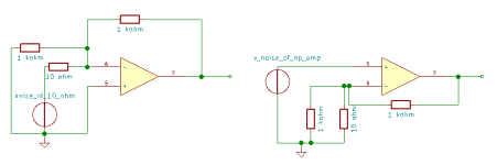
Because of the negative feedback. The 10 ohm resistor and 1 kohm feedback resistor set a gain of ideally -100 for the noise of the resistor. The equivalent input voltage noise of the op-amp gets amplified 102 times; model it as a noise source at the positive op-amp terminal, switch off all other sources and you see that for the op-amp's noise, the circuit is a gain of 102 non-inverting amplifier.
Attachments
Last edited:
Because of the negative feedback. The 10 ohm resistor and 1 kohm feedback resistor set a gain of ideally -100 for the noise of the resistor. The equivalent input voltage noise of the op-amp gets amplified 102 times; model it as a noise source at the positive op-amp terminal, switch off all other sources and you see that for the op-amp's noise, the circuit is a gain of 102 non-inverting amplifier.
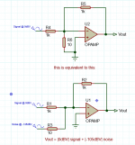
Ahhh! I can see it as a summing amplifier, amplifying the source 'signal' via the 1k a factor -1, amplifying the 'source' [10R noise gain resistor] a factor 1k/10.
As in the attachment?
Jan
Attachments
Last edited:
Ahhh! I can see it as a summing amplifier, amplifying the source 'signal' via the 1k a factor -1, amplifying the 'source' [10R noise gain resistor] a factor 1k/10.
As in the attachment?
Jan
Yes!
Noise gain is the output voltage change divided by the differential input voltage change, assuming the amp is out of circuit and the output voltage is driven by a test signal.
If you model the noise voltage being between the two inputs, this is the amount it must be magnified by the opamp such that the feedback exactly cancels it - i.e. the closed-loop gain the noise is subjected to.
I think a lot of texts are very obscure about this, its a simple concept. Signal gain is about the output relative to the input node, noise gain is about the output relative to the differential input voltage, which are both properties of just the feedback network if the opamp is ideal (infinite gain).
Noise gain is also the critical parameter for stability, the opamp doesn't know about the signal gain, it only knows about the noise gain. For instance the NE5543A is stable for noise-gains above 3.
There are some subtleties this notion fails to capture, for instance the effect of capacitances between amp internals and the supply rails are ignored in the statement "the opamp doesn't know about the signal gain, it only knows about the noise gain" - its an idealization.
A simple follower has a noise gain of 1, but a unity gain inverter has a noise gain of 2. The inverter circuit is a resistor divider that halves the output at the opamp input. For instance the NE5534A should be stable for non-inverting gains down to 3, and for inverting gains down to -2
Thanks Mark, that's very helpful.
My confusion was from reasoning that whatever is 'hard' between the input pins (noise or otherwise) is amplified by the opamp ol gain. It has to; that is the way the opamp is build.
The noise gain resistor is 'hard' between the pins, but the noise source it is associated with is not; this noise source should be considered in series with that resistor.
As in my post 4 attachment. It is that resistance that allows the feedback loop to work on this source.
Makes all the difference.
Jan
Last edited:
- Status
- This old topic is closed. If you want to reopen this topic, contact a moderator using the "Report Post" button.
- Home
- Source & Line
- Analog Line Level
- Why does noise gain not amplify noise?