Sony SCDXB 940 SACD player. The digital filter is fed from the analogue +- 12V regulators via +-7V and 3.3V regulators.
I am trying to remove clock related pulses from the analogue power supply which finds it way into the output via OPA2604 filter/buffer. The stock unit is littered with inductors and capacitors to provide isolation of each power supply stage.
Having tried lots to further bypass opamps and regulators, I am wondering why there are 560 Ohm resistors connecting the inputs and outputs of the +-7V MSF 7X07 regultors and whether this is the problem. These regulators are fed from the analogue ones and isolated by 30 uH inductors at their inputs.
Can anyone wiser than me explain the purpose of the resistors and why they are used only for this specific set of regulators please. I am intending to remove them once I know why.
Jocko Homo said:Are you sure that your 'scope leads aren't picking these up?
Jocko
Yes, I first noticed the problem when measuring unweighted THD which was only -80 dB below reference; high for a cd player. Display on scope direct show sabout 30 mV pk-pk of nasty high frequency spikes corresponding to clock freq. Weighted, the unit meets spec. I suspect the sonic signature to be related to the noise; hence the desire for a cure. The same pattern obtains in the analogue power supply rails, the filter/buffer output and can be made much worse by further decoupling between the V+ and V- rail of the filter/buffer opamp.
Another possibility is that the opamps themselves are the cause. They are OPA2604s with 20 MHz bandwidth. I have come across this problem of roque opamps in the SCD777ES but SMT mounting means that I don't want to remove and refit unless I have to.
I can't post schematics as I don't have a scanner. The issue is:
Why does anyone want to connect input and output of 78 07 and 7907 with a small SMT resistor of 560 Ohm with a voltage differential of 5V.
The unit used appears to be 1% film as well!
Resistors between input & output of regulators
Hi fmak,
These resistors are a silly habit of Sony. Silly beacause they provide a path for spikes and other garbage from the unregulated supply to enter the regulated supply. I had one such resistor too in the +5V digital supply of my Sony CDP. I removed the resistor and replaced the regulator by LT1086. Much better.[not pin compatible!] Maybe they have done it as the regulator gets overheated otherwise. Another silly Sony habit: inadequate cooling (too small heatsink) Hope this helps as I owe you one!
Hi fmak,
These resistors are a silly habit of Sony. Silly beacause they provide a path for spikes and other garbage from the unregulated supply to enter the regulated supply. I had one such resistor too in the +5V digital supply of my Sony CDP. I removed the resistor and replaced the regulator by LT1086. Much better.
[not pin compatible!] Maybe they have done it as the regulator gets overheated otherwise. Another silly Sony habit: inadequate cooling (too small heatsink) Hope this helps as I owe you one!Re: Resistors between input & output of regulators
Can't be overheating problem as the resistor will not take any appreciable current. Must be an other 'technical' reason????
Elso Kwak said:Hi fmak,
These resistors are a silly habit of Sony. Silly beacause they provide a path for spikes and other garbage from the unregulated supply to enter the regulated supply. I had one such resistor too in the +5V digital supply of my Sony CDP. I removed the resistor and replaced the regulator by LT1086. Much better.
Can't be overheating problem as the resistor will not take any appreciable current. Must be an other 'technical' reason????
Re: Re: Resistors between input & output of regulators
fmak said:
I removed the input /output resistors and this has no effect. I am beginning to suspect instability in OPA2604. Has anyone found a similar problem. The noise spikes are low level high frequency but look very nasty.
There are some older audio amateur articles from the 90s that dealt with noise in digital equipment power supplies as well as some mods and super regulators. These are great for reference if you plan on going deep into digital and can be found at www.audioxpress.com in their backissue section.
Elso is right. Designers often use resistors in parallel with series regulators to either help dissipate the heat or keep the maximum load current within the limits of the regulator. It's cheap. Sometimes pennies count.
The resistors do not really add a path for spikes. Combined with the output bpass capacitors an RC low pass filter is created. Very little of the RF gets through. Of course, it depends on the quality of capacitors.
The best way to eliminate clock pulses & such is to use ferrite beads. They work better than inductors at RF. On the other hand, Jack is probably right - it's your scope probes causing the problem.
jh
hagtech said:Elso is right. Designers often use resistors in parallel with series regulators to either help dissipate the heat or keep the maximum load current within the limits of the regulator. It's cheap. Sometimes pennies count.
The resistors do not really add a path for spikes. Combined with the output bpass capacitors an RC low pass filter is created. Very little of the RF gets through. Of course, it depends on the quality of capacitors.
The best way to eliminate clock pulses & such is to use ferrite beads. They work better than inductors at RF. On the other hand, Jack is probably right - it's your scope probes causing the problem.
------------------------------------------------------------------------------
Thanks for the help. If it is the leads, how do I get rid of the pickup. I have tried ferrites on these and inductors on the output of the opamp without success. Needless I have re-routed cable runs etc. This will be the first time I have come across the problem on any CD or SACD player. The spikes appear whether the top is on or off with no change in level. As I said, thid unit has more inductors and bypassess than I have come across normally.
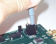
Like this: (see pic)
I use this special ground lead attachment for high bandwidth work. And the probe is a special 5k ohm 1.5GHz design. I also have a 500 ohm 3.5GHz probe that works even better on low impedance (e.g. power supply rails) signals. Photo shows a clock & data recovery circuit running at 2.5Gbps with 100ps risetimes, and a Tek P6057 (rare) probe.
What you really need is a very expensive and professional differential probe.
Or try this: remove the probe "hat" and ground lead, use a piece of 22AWG bus wire (or maybe even solder) and wrap it around the grounding ring near the tip pf the probe. Leave one end hanging out near the probe tip. Now you have the tip and ground a few millimeters apart. The ground lead is as ashort as you can make it. This will help greatly in reducing the pickup from the probe.
If you have switchable probes, change to the "1x" setting. You have to get the impedance down.
Another approach is to make your own probe out of 50 ohm coax. This is a bit more involved and requires a 50 ohm termination on your scope's input. Email me if you want details.
Attachments
Elso, keep in mind when looking at a circuit that (in general) engineers a not idiots. EVERY part there is there for a reason and has a designed purpose. Whether the designer's method can be improved is where tweaking can be beneficial, but I can assure you Sony do not do this as a "Silly Habit". As suggested, from the description it is an RC filter used to decouple the supply. A coomon way to improve this is to replace the resistor with an inductor. Due to the inductor's internal resistance, replacing forms an RLC filter. Adding a ferrite to the lead of the inductor is most beneficial in attenuating any RF that may be picked up by the component leads.
Hope this helps.
Cheers,
Pete
Hope this helps.
Cheers,
Pete
Extra parts
That's right, Wadia puts in extra parts to screw up the sound because they can aford to. By the way, there are plenty of engineers that are idiots. I have worked with enough of them to know!
For probing high frequency noise:
http://www.sigcon.com/articles/edn/probing_for_noise.htm
http://emcesd.com/
H.H.
I must side with Elso and HH in that just because an engineer does something one way, doesnt make it the best way! Sure that resistor forms part of a low pass filter but dont assume that it's doing a good job of it.
RULE #1. Dont assume anything anyone has done is the best way of doing it until you've tried all the other ways of doing it...
Less parts is not always better and more parts is often not as good.
I'll leave the rest to the individual.
RULE #1. Dont assume anything anyone has done is the best way of doing it until you've tried all the other ways of doing it...
Less parts is not always better and more parts is often not as good.
I'll leave the rest to the individual.
AudioFreak PLEASE reread my post. You will see the line
"Whether the designer's method can be improved is where tweaking can be beneficial". Although I thought it clear, I will restate again. The parts are there for a purpose, in this case (from my understanding of the circuit description) the resistor forms part of a filter network. NO Engineer will simply throw in some parts just to fill up board real estate, if they did they would last about a week in their job. Harry if you have met "Plenty of engineers" who are idiots then I am truly sorry for you.
An engineer, though clearly not the "idiots" that Harry knows so well, has 2 constraints (amongst others) when designing that may not apply to us. One is cost, and for Japanese designs this is especially true. Another is the designed purpose of a particular circuit area. Clearly we can often improve circuit performance by using higher quality components (ie more expensive), and the improvements in this area are often most worthwhile. Indeed considering the improvements versus cost, one is sometimes left to wonder why higher quality parts were not specified in the first instance. The second constraint is the design objectives of that group of components. Some functions we may not consider applicable to us. For example the output muting area of a CD player may be removed and we may be quite happy to live with a few clicks and pops during track selection. Nevertheless, those components were originally there for a purpose.
Naturally there are many topologies available to perform a certain circuit function, and that used by the engineer may not always be what is considered the ideal in that situation. Often this is a subjective area, as different designers will have different opinions on what they consider “ideal” for that function. An amplifier is a good example in this area, where there are hundreds of variations of basic themes. It should be considered that in large electronics manufacturers an engineer may be on the design team of a CD player one month, a GPS the next month, and a television the following month. While areas of a circuit may be common between such diverse designs, what is considered good design for, say, a power supply of a GPS receiver may not be considered ideal in another application such as a CD player. Again, this is where tweaking or even completely redesigning a circuit area can provide great benefits. However before labelling the engineer an “idiot” or believing a multi-billion dollar company that costs down to fractions of cents the proprietor of “silly habits”, try to put yourself in the engineer’s shoes. When looking at a circuit ask what was he or she trying to achieve here, is it applicable to me, and can I improve it?
Cheers,
Pete
I saw that line Pete but my opinion still stands.... Just because Sony is good @ marketing and managing the bank balance, it doesnt make them good @ designing decent audio equipment...
Further more, Sony etc. have many silly design habits that in a round about way let them cut corners in the name of integrating a "design feature".
Further more, Sony etc. have many silly design habits that in a round about way let them cut corners in the name of integrating a "design feature".
Engineers
I didn't say all engineers are idiots........ I am well aware of the requirements of cost reduction since I designed line cards for a multi-billion dollar international telecom company. I used some parts that cost less than a cent and I still minimized the number of them. The last card I worked on was produced in quantities of over a million per year. Sony does a good job on thier products and I own several of them.
"NO Engineer will simply throw in some parts just to fill up board real estate, if they did they would last about a week in their job."
With the help of marketing, I have seen just that done. Engineering breeds complexity. Case in point, look at the simple and elegent design of some of John Curl's work for Levinson and look what happened to it after some other engineers "improved" it. Some companies think that a customer paying thousands of dollars expects to a complex circuit for his money. It is interesting that a very good sounding power amp can be built less than a couple of dozen transistors, yet many engineers find ways to use over a hundred.......
H.H.
What are some of these "silly habits" that they do all the time?
Remember this is from YOUR perspective, and, once again, can only say that your perspective may not be the same as the engineer's. So what makes a "decent" CD player then? One that sounds absolutely 1st class? Most here, by the fact that we read and post on this forum possibly think so. So therefore everyone in society would be happy to spend, say, $2000 on a CD player? Clearly not. Indeed if the average cost of a CD player was so high the format would probably die.
The designers aim to produce an audio component within a cetain price range to satisfy that segment of the market. In most cases the end result is very good indeed once one factors in the cost. Can they be improved? Almost certainly yes, but to label the engineers idiots who simply throw compenents in for laughs is quite a call indeed.
Harry. 99.9% of consumers have no idea what is inside the case, and have no interest in how many components are used. While I remember the days of advertising how many transistors were used in a radio, those days are well and truly over. Once again, if more components are used, they are used because the engineer believed they would perform some useful function.
Personally I try to follow the philosophy of "less is better", so we are not in disagreement there. The example you provide regarding an amplifier is a good one to illustrate design objectives. We both know that often the amplifier with a few components will generally have worse specifications than the more complex version. So if you were aiming to design to fulfill a set of specification you would fail. Which one probably sounds better? We both know the answer to that.
Cheers,
Pete
- Status
- This old topic is closed. If you want to reopen this topic, contact a moderator using the "Report Post" button.
- Home
- Amplifiers
- Solid State
- Voltage Regulator Problem?