Hey,
I bought relatively cheap, almost free of charge Sansui G-301/G-3500 stereo receiver in unknown condition. Visually unit is in really good shape. Components were not burnt or anything. I could tell they were old and dusty.
I just decided to get this unit to work on a new project. I have restored one unit before this, so I'm not very experienced.
So I tested the unit; in the beginning there was major crackle present on both channels. Just to know what I'm dealing with. So I've carefully recapped whole preamp, power output stages and majority on receiver stage.
After some component updates I tested the unit again. Not much to be said at this point, just power restored to both channels, but sound was distorted.
I went on measuring transistors legs soldered on the power output / driver stage. So I find out TR13 was blown. Measuring zero ohms between one leg pair. I popped these out of the stage to make sure they're blown and yes they were. I have soldered the new parts there and now left channel restored to crackle free condition and left channel seemed alright basically. No popping just clean sound, however right channel is still crackling and less power output there. After some more measurements TR12 seemed as bad as TR13.
So I have replaced these 2 transistors now and tested the unit again, well resistor R74 gave the "magic smoke". I turned off the unit. The unit was on perhaps 15-20 seconds and smoke came out when I tried to increase volume, but noticed right channel sounded good, no distortion present for that tiny moment, just lack of power and then smoke came out from the power stage.
Output transistors TR17 and TR16 measure both zero ohms between 1-3 legs. I popped these off the board. Now I have ordered the new components. I have visually inspected the resistor R74, there's tiny area of black residue due to "minor" heat damage. I measure approximately same readings from the resistor R73 and R74 soldered in unit. What you think should I replace the R74 even if it seems like "okay" by numbers?
Should I pop out more components for testing?
I am aware I haven't been careful enough, causing major damage to the new components possibly. However I feel there might not be too much damage done yet. I was able to turn off the unit as soon as I saw the smoke coming out.
Could be I'm just dreaming....
Anyway..
I'm aware of the dim bulb tester and basics of it. All the instructions on DIY bulb tester seem to be for american standard 120V and there's polarity in them. How should I wire it for 240V standard? Because the part which I don't understand is here I can insert AC plug in both ways to outlet in wall. Both AC socket plug pins are the same size. DIY diagrams show the bulb should be connected in series to the "hot wire". How in earth this is done, since I can insert the plug to wall outlet in both ways? To me it seems that diagram is polarized. Only the ground pin is always the same.
All help is appreciated.
Thanks.
Attachments
AC is not polarized, you've been reading too much american stuff.
Put the light bulb in series with one of the wires on the power cable. Just cut one of the wires off (doesn't matter which), and install the two cut ends of your cable on each side of a light bulb socket. Easiest to do this with an extension cord, so its reusable, and you don't ruin the equipment. Don't die here, do it properly and safely.

Put the light bulb in series with one of the wires on the power cable. Just cut one of the wires off (doesn't matter which), and install the two cut ends of your cable on each side of a light bulb socket. Easiest to do this with an extension cord, so its reusable, and you don't ruin the equipment. Don't die here, do it properly and safely.
Last edited:
Thanks for the info and diagram.
I was able to find out similar diagrams, for example:
http://www.radiolaguy.com/images/misc/TestSocket.jpg
Now that's easy to build. I have a bulb socket available from old lamp and I guess 60W bulb is good to go.
I wasn't so sure until now, since there was no voltage rating in the diagram or picture description. American bulb tester diagrams show different size AC socket pins and couldn't find 240V mentioned anywhere and I'm no electrician, so it seemed very puzzling.
Now waiting in for the new parts and starting this thread decided to test few more resistors and I can say R67 is also shot. Multimeter giving OL. R68 could be shot as well, readings jump heavily. To be 100% sure, I should desolder one leg free. Aware of that.
Meanwhile good time to build that bulb tester, since I don't want the new output transistors to fail at first thing and get some silicon grease for the transistors")
I was able to find out similar diagrams, for example:
http://www.radiolaguy.com/images/misc/TestSocket.jpg
Now that's easy to build. I have a bulb socket available from old lamp and I guess 60W bulb is good to go.
I wasn't so sure until now, since there was no voltage rating in the diagram or picture description. American bulb tester diagrams show different size AC socket pins and couldn't find 240V mentioned anywhere and I'm no electrician, so it seemed very puzzling.
Now waiting in for the new parts and starting this thread decided to test few more resistors and I can say R67 is also shot. Multimeter giving OL. R68 could be shot as well, readings jump heavily. To be 100% sure, I should desolder one leg free. Aware of that.
Meanwhile good time to build that bulb tester, since I don't want the new output transistors to fail at first thing and get some silicon grease for the transistors
AC is not polarized, you've been reading too much american stuff.
Well it is and it isn't depending on the context. When we speak of AC power being polarized, it means one conductor is hot and the other at ground potential. Because in the American electrical system as well as many other countries as I understand tie the neutral to the ground at the service entrance. This provides a fault path to trip a breaker should enough current flow in the ground conductor. Otherwise a dangerous ground fault would not trip the breaker.
So if building a series light, you would want the lamp in the hot lead not the neutral lead. Just a bit safer shock wise that way in case you contact with an external ground. At least then the current flow though YOU is limited by the bulb resistance.
As I understand from information documents, the electrical supply system in Finland is similar to many European countries where a "Shuko" plug system is used for up to 16A domestic appliances. The polarity of the AC socket connectors is random, i.e either could be called "Live" or "Neutral" because there is no MEN system where one AC supply cable would be strapped to earth at multiple points in the supply grid and at the meter box.
Power plug & outlet Type F (Schuko) - World Standards
In other words, you don't have a "Live", "Active" or "Neutral" pin. Both are "Live" and equally dangerous. In any case, lightbulb wiring should be connected to a standard, approved type of light socket that is fully insulated and enclosed or surface mounted to an approved type of insulated box for the 220V supply used.
We all need to know what we're doing when we take mains electrical safety in our own hands - not like when we have a transformer that isolates the mains supply from our electronic device
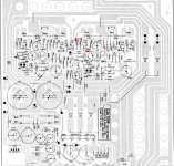
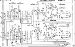
Being one of the channels OK, compare all drivers and output transistors (as well as neighbour resistors) from both channels, without the need of removing any component. Also check voltages, as stated on the schematic (only shown on the right channel/lower part).
Attachments
The polarity of the AC socket connectors is random, i.e either could be called "Live" or "Neutral" because there is no MEN system where one AC supply cable would be strapped to earth at multiple points in the supply grid and at the meter box.
Power plug & outlet Type F (Schuko) - World Standards
That's what we have here, true.
I am certain the problem lies on the output stage. I started measuring resistors near output transistors. Resistors from R69 to R72 all 4 (220 ohm) were toasted or heavily out of range. Also R75 near output transistors (6.8 ohm) and resistors closer the power source R67 and R68 were toasted. I replaced all these with correct wattage resistors. Thanks for the tip.
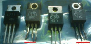
I received the new output transistors from Ebay. The replacements came from UK. The old ones underlined red on the picture are definitely toasted.
I am worried a bit since on the schematics appropriate transistor TR17 replacement is a transistor 2SA771 with Q or Y, but off the Ebay comes something "09H" and it's not Sanken. Not printed at least. The other shipped, TR16 is Sanken and is alright with correct letter. What you think is TR17 going to be a problem?
However, now I have conducted the first test run with the amp wired to the dim bulb tester without speakers. It's not very pretty looking, but obviously it did what I made it for. 60 watt bulb gets bright for 1 second as I turn the unit on and then it dims down and stays dim. No smoke! Good sign.
I noticed some warmth over the heatsink and the unit was on maybe for one minute tops. No speakers connected and volume very low. Is it all good?
Should I let the amp stay powered with the dim bulb tester for longer perioid of time or should I just test the unit with speakers connected?
Attachments
Yeah... finding outputs is gonna be fun. I'd start by looking through what Digikey has for Sanken TO-220's, see if you can find a 60 to 80 W device pair that's good for at least 6A. That supply voltage is a bit out of range of generics like the TIP41/2, which would likely overstress the drivers due to low Hfe at high current. If you never never ever ran 4 ohms they would be ok, but even then distortion would be higher than with the originals. Might even try the Fairchild C5200/A1943 clones which are available in a variety of packages - including the TO-220.
Sure are fake They don't even have the insulated package so even if they work, only a desperate person would try to use them and certainly not for a quality audio repair.
Here's Sanken's current replacement types: http://www.semicon.sanken-ele.co.jp/sk_content/2sc4511_ds_en.pdf
http://www.semicon.sanken-ele.co.jp/sk_content/2sa1725_ds_en.pdf
Don't buy from Ebay sellers - use reputable distributors of traceable stock components like Digi-key, Mouser and 2SC4511 - Power Transistor 80V 6A.
They don't even have the insulated package so even if they work, only a desperate person would try to use them and certainly not for a quality audio repair.Here's Sanken's current replacement types: http://www.semicon.sanken-ele.co.jp/sk_content/2sc4511_ds_en.pdf
http://www.semicon.sanken-ele.co.jp/sk_content/2sa1725_ds_en.pdf
Don't buy from Ebay sellers - use reputable distributors of traceable stock components like Digi-key, Mouser and 2SC4511 - Power Transistor 80V 6A.
Here's Sanken's current replacement types: http://www.semicon.sanken-ele.co.jp/sk_content/2sc4511_ds_en.pdf
http://www.semicon.sanken-ele.co.jp/sk_content/2sa1725_ds_en.pdf
Don't buy from Ebay sellers - use reputable distributors of traceable stock components like Digi-key, Mouser and 2SC4511 - Power Transistor 80V 6A.
Ok, no transistor shopping from Ebay. I didn't know this. It was electrical components shop and 99% of the feedback was basically just good.
Other replacement components I got from a local electronic shop. The guy told me some audio gear are very intolerant for the transistors, which are not on the schematics.
Do you think if I purchase 2SA1725 to replace 2SA771 and 2SC4511 to replace 2SC1986 will definitely work on this unit? Is it more likely just to buy and solder them on for a test?
I have very generic mini hifi speakers rated 6 ohms max input 80W for testing. I shouldn't connect these speakers to the unit at all with fake transistors?
I would take the fakes out without testing them, because when they blow up they may cause further damage to the rest of the amp.
Ebay feedback isn't a good way to see what you get, because most people buying fakes aren't aware of it and when the parts fail, they blame themselves rather than the seller.
Ebay feedback isn't a good way to see what you get, because most people buying fakes aren't aware of it and when the parts fail, they blame themselves rather than the seller.
Last edited:
No one can offer a guarantee more than to say that they are Sanken's recommended alternative components as stated on their website list of discontinued parts. I doubt anyone has ever tested your model amplifier specifically to verify this compatibility on yours or any other similar obsolete amplifier using them. This would only be done by manufacturers for models still in production. See for yourself: Discontinued Products ?Sanken Electric....Do you think if I purchase 2SA1725 to replace 2SA771 and 2SC4511 to replace 2SC1986 will definitely work on this unit? Is it more likely just to buy and solder them on for a test?......
The original parts are obsolete so you need replacement types anyway. These are the ones recommended by Sanken and will definitely work because the datasheet specifications say so.
The main point being made though, is not so much the transistor type, but avoiding any bad and fake parts. The original parts could be replaced by a few common types of TO220 transistors, as wg_ski suggested. Unfortunately, most buyers have no clue what they are getting because they are focused on the part number and they look fine in the fuzzy thubnails and even seem to work correctly until high power is tried, when the flea-power junk inside just burns. That's what you could be getting.
Many buyers seem to have have trouble understanding that obsolete and hard to find parts can't be sold in endless volumes at incredibly cheap prices. It just does not make sense but somehow, all miracles are possible on Ebay, Aliexpress etc.
No one can offer a guarantee more than to say that they are Sanken's recommended alternative components as stated on their website list of discontinued parts. See for yourself: Discontinued Products ?Sanken Electric
The original parts are obsolete so you need replacement types anyway. These are the ones recommended by Sanken and will definitely work because the datasheet specifications say so.
Many buyers seem to have have trouble understanding that obsolete and hard to find parts can't be sold in endless volumes at incredibly cheap prices. It just does not make sense but somehow, all miracles are possible on Ebay, Aliexpress etc.
Thanks for your input and detailed information.
This helps me a lot. I'm really not so experienced on audio repairs, but naturally you look for reference like link to the manufacturer's site. I just want the information to be accurate you know.
Welcome, I will pull those fakes out without testing them further and place order on the new ones that Ian pointed out. I think I will use Profusion, since their shipping rates seems moderate plus then I will get spares enough. I need to order 10 pcs each transistor. Then it will cost like 25 euros with shipping. Digikey charges 16 euros for just shipping so....
I don't want to destroy the driver board anymore with the new components on it. I did a lot of work on replacing those toasted resistors and transistors already. Waiting is no problem, I have a primary audio amplifier, which works just fine.
I will return after I have replaced the output transistors.
So now I have the new and original Sanken replacement output transistors soldered on.
Sansui is back to life!
Thanks to everybody who helped me here.
Receiver is incredibly sensitive. It picks up clear stereo reception with no antenna with many stations. I'm blown away. Everything works perfect now!
I must say there was definitely something seriously wrong with the Ebay transistors. Since now with the original output transistors hovering the palm of my hand over the heatsink I feel no heat at all. Even tho the unit's been on for an hour. With the faked Sanken transistors there was much more heat over heatsink. And it was on for less than a minute when I tested it. I can tell there's great difference.
Now looking for new projects
Good work and glad that when you found the problem with the parts you bought, that you posted the result here. Others may be more careful as a result.
As someone who has done my share of audio repairs, I can say how dumb it is buy cheap crap parts simply because the seller posts a few pics (not always their own) of goods that only resemble original parts, with no reference to a specific datasheet, brand or statement of origin.
As someone who has done my share of audio repairs, I can say how dumb it is buy cheap crap parts simply because the seller posts a few pics (not always their own) of goods that only resemble original parts, with no reference to a specific datasheet, brand or statement of origin.
Thanks. My luck didn't run out completely on testing with the fake transistors. I replaced them without further tests to prevent any damage.
One indication of a fake transistor obviously is also when the printed text on the transistor is not centered. Here you see, the text is not centered on the Ebay 2sc1986.
Anyway, now I realize I haven't done any adjustments with the amp.
I don't know whether I should do anything to adjust it. Listening to the amp I can't hear any difference between channels. They sound like everything is alright. The heatsink is cool (can be touched by hand) after the unit's been on 1 hour. In the service manual there's instructions how to bias the amp. The measurement points (the resistors) by the heatsink are covered all the way. So it seems problematic thing to do, unless pinching the insulation upwards and for this approach I should get alligator clips. It feels awkward thing to do.
I measured the DC offset from speaker terminals and on the left I have 48mV and on the right 0mV. I realize I should do something here, right?
Previously I told you about the smoking resistor before the DBT arrangement. There's a visual sign of burn, black residue damage on the side of the resistor (R74), but measuring it by multimeter readings seem alright (~6.9ohms).
Maybe it has something to do with the DC offset?
Should I try to adjust anything or just let it be?
You need to set the bias after replacing output transistors.
The ceramic insulators on the leads on the emitter resistors? Easy. Just squeeze them with something and they'll shatter into a thousand pieces. After that, measurement will be easy, but use mini grabber leads or you will slip and kill the amp anew.
Clean the bias VR before touching it. Just spray it down with some alcohol or contact cleaner. Only turn it with microscopic movement, as any sudden larger moves will turn it up too much and kill the amp.
Thanks for the tip
I'll try to be careful with it.
I believe speakers need to be disconnected while adjusting the bias?
I have a can of CRC 5-56.
However I should buy lubrication spray (PRF 7-78) for the pots,
so I figure it's better to be used with VR, since it will not conduct electricity.
I'll try to be careful with it.
I believe speakers need to be disconnected while adjusting the bias?
I have a can of CRC 5-56.
However I should buy lubrication spray (PRF 7-78) for the pots,
so I figure it's better to be used with VR, since it will not conduct electricity.
- Status
- This old topic is closed. If you want to reopen this topic, contact a moderator using the "Report Post" button.
- Home
- Amplifiers
- Solid State
- Vintage Sansui restoration