I have just come across a rather unusual schematic for a single valve amp that has some unusual features. This is a Telefunken design from the 1950s. I would like some help understanding some of the connections as they are pretty different from things I have seen before.
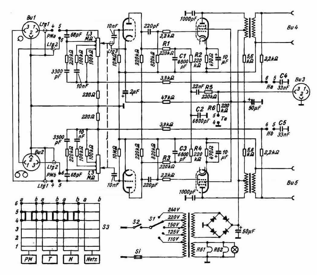
The OPT seem to have a primary connection to the output screen something like ultralinear but not quite. It is also grounded via a capacitor one way and a resistor capacitor the other way why would you do this?
There are also some RC networks at the potentiometer I think these must be some kind of tone controls but not sure how they are supposed to work
I am thinking about a version of this schematic for my bitsa amp project if I can figure out what to omit to make it much simpler.
Thanks for your help and knowledge
Unsolicited opinion: its ridiculous … and some of the components won't even be available for purchase. For example, the 4 (3? 5?) tap combo volume/tone/presence control up front. Clearly it is an amplifier with NFB; clearly it relies on a very sensitive triode first stage to get most of the amplification done. … as I said … rather ridiculous on the surface. ESPECIALLY in the context of your statement, “I'm thinking of using this for my XYZ doohickey, if only it can be substantially simplified” (paraphrased). That last bit is what makes this doohickey ridiculous. Just start with a design better suited to match your application to begin with.
GoatGuy
GoatGuy
Folks, Thanks for the quick feedback! Goatguy you I do not disagree that this looks ridiculous however it seemed to be a design that lasted some time in production. My interest in it is that I have a lot of bits that I was looking to build into an amp as a learning exercise and they seem to fit with what is in this schematic, specifically the output transformers which have this strange primary tapping and a power transformer that has no centre tap and two 6.3V taps. This thing is only good for a watt or two so will probably be a desktop amp to power computer speakers and I have a couple of those from an apple set up, cute little spherical things that came with a USB amp that has no software support anymore. I am guessing I can just forget the tone control stuff and use a conventional pot
for volume. The NFB link for the OPT secondary looks like it goes to the bottom of the volume pot. Any idea how this works? Does it need the tone networks to function? There are some similarities with the Mullard economical 3W amp schematic from 1962 which was the other one I was looking at. This uses an RC network in the NFB to provide bass tone control.
for volume. The NFB link for the OPT secondary looks like it goes to the bottom of the volume pot. Any idea how this works? Does it need the tone networks to function? There are some similarities with the Mullard economical 3W amp schematic from 1962 which was the other one I was looking at. This uses an RC network in the NFB to provide bass tone control.
An externally hosted image should be here but it was not working when we last tested it.
Member
Joined 2009
Paid Member
The 1st schematic looks like it is using an assymetrical P-P OT for SE usage, by balancing the OT DC with the 5.6K Ohm resistor supplying DC averaged (50 uF) grid 2 currents. So maybe loosing 1/2 the power output into the resistors.
I don't see it like that. It's weird alright, but looks to me like the OPT does double duty as the load for the power tube plate and also as a B+ filter choke for the supply to the driver tubes and the output tube screen grids.
Yeah, agree, hum bucking for sure.
But the screen current is also opposing the output stage plate current in the OT, so the SE core gap can be smaller (giving higher inductance for better low freq.). And that 5.6K resistor is going to absorb some output audio power. EL Cheeso design. A huge amount of design work to reduce the cost by $5.
Not sure why AVO111 wants to use that ECL82, but for $3 or $4 (6HJ5, or 21LG6, 26DQ5, 6CB5, 12GT5, 12GE5, 21JV6, 21HB5, 6EX6 or 6GY5) and $1 (12HL7) one could build the best 5 Watt SE amp on the planet. Or double that, for the best 100 Watt P-P amp cheap money can buy (DCPP board or Pete's P-P driver board).
http://www.pmillett.com/ppdrv.htm
Last edited:
Concurring with views regarding the OPT tap, but I do find the input circuit rather strange.
As Wavebourn said, it resembles the usual loudness control - except for the fact that as shown it operates rather the opposite way!
One can view the amplifier as an inverted topology, with the summing point at the junction of the 3,9K and 220E resistors. This is a low impedance point, 3,9K being the feedback resistor and the input potentiometer the input series resistance. With the input grid near the bottom of the pot the topology holds. As the slider is advanced upwards the input series resistance not only decreases but the NFB also decreases, thus increasing signal volume. (One is presuming a low input feeding impedance.)
But then at low volume - say with the pot slider at the 100K tap position, where one would expect greatest volume increase for l.f. as per loudness, the input attenuation is in fact increased as frequency decreases. (The impedance of the 3,3nF and 10nF series caps increases with lower frequency, increasing the 'series' input resistance and thus decreasing the volume instead of the other way round.) I presume that the schematic is drawn correctly. With the volume slider at max. position, NFB is minimum, then increasing l.f. where it is not normally desired by increased NFB at mid. frequencies. The input impedance is thus also not constant with frequency, etc.
??? There are several ways of implementing such a circuit; in this case I would imagine the more normal way of feeding NFB to the input tube cathode and leaving the grid 'free' to normal circuitry would have been better. (I would have liked to see the design response graphs for the various settings - easily simulated although I have not done that at this time.)
Last edited:
Hello ,
here is the original amp :
TC: Telefunken S81 S82 S80 integrated tube amp - www.tube-classics.de
Kind regards , Alexander .
here is the original amp :
TC: Telefunken S81 S82 S80 integrated tube amp - www.tube-classics.de
Kind regards , Alexander .
Johan;
I did similar volume control in a table-top SS amp, it works exactly as I described, increasing gain on lows on low volume. It is not a pesky "F&M Curves' Loudness", the original German purpose of this control was to get a better bass on low volume using an "extra power" to drive speakers below their Fs. I.e. the louder, the less equalized.
I did similar volume control in a table-top SS amp, it works exactly as I described, increasing gain on lows on low volume. It is not a pesky "F&M Curves' Loudness", the original German purpose of this control was to get a better bass on low volume using an "extra power" to drive speakers below their Fs. I.e. the louder, the less equalized.
Alexander, yes that is the amp that the schematic comes from. It is very cute looking, I doubt that mine will look so good!
Johan, how did you connect the loudness elements to the volume pot? I was thinking of omitting them however if it is doable and works then why not keep them?
Thanks Avo 111
Johan, how did you connect the loudness elements to the volume pot? I was thinking of omitting them however if it is doable and works then why not keep them?
Thanks Avo 111
Wavebourn,
I did notice the multitap topology - wish such controls were still available. As you imply, the 'centre-tap-only' way is far from ideal. (OT: I spend money these days and rather use a 28-position Elna rotary switch deck with which I can tailor the response as desired etc. You will know.)
But my take is as explained. It would be most kind of you to point the error in that; I am careful to disagree with someone like you!! I will think again when more time. Best to sim.
Avo111,
Apology if I was unclear. I did not construct/sim. the circuit yet; said I would like to. I use a separate (older) off-line PC for that but it is at present on the blink.
From input to the 1'st tap we have a resistance that with a Zobel gives in that point a frequency response with low boost, you can easily calculate. Then, to the second tap we have more resistance that with the second Zobel gives more boost on lows. Feedback has nothing to do with it, it does not change the frequency response since grid-cathode resistance is huge compared to the volume control. Ideally, we want 12 dB/Oct below Fs, but such simple trick can's get the ideal. But anyway, Germans started to use such a "low boost" a long time ago, making cheap speakers to sound "bassier" on low volume. Later somebody in USA "guessed" that it was about F-M equal loudness curves, and screwed the idea down. 
I used something similar, but in my case a volume control also was adding some positive FB by current.
I used something similar, but in my case a volume control also was adding some positive FB by current.
Last edited:
Member
Joined 2009
Paid Member
I hate to say the obvious, but some things made in Germany during the 1950's were simply not so special. For example most of the consumer turntables made by Braun... look kinda cool... sound kinda crap.
I would suggest this amp falls into this category. I personally would design and build something else from scratch with whatever components you have on hand.
Why not simply list what you have and not let this old schematic be inspiration?
I would suggest this amp falls into this category. I personally would design and build something else from scratch with whatever components you have on hand.
Why not simply list what you have and not let this old schematic be inspiration?
OK, Thanks for the help Soulmerchant the bits I have are as follows:
1 Power Transformer 250V no centre tap 100ma, 2 X 6.3V at 1.5A
2 pair of output transformers that appear to be the same as those in the schematic with a short tap on primary
3 2 X EZ81 rectifiers
4 1 X mullard ECL82
5 4 various KT88
6 1 pair EL34
7 4 X Russian 6H9C
8 1 X Chinese 6N9P
9 2 X Chinese 12AU7
10 1 X Chinese 12AX7
The challenge is finding something suitable for the OPTs. Originally I thought they could be used with the EL34 but really I don't think they are up to it. Aim is to get a low power amp with volume control for use with either a bluetooth dongle or airplay device and connection to a computer headphone output. I have a rather nice pair of spherical Apple speakers that measure around 7 ohm DC that used to be driven by a USB amp which is no longer software supported. They sound OK on my other valve amp with single ended KT88.
This is a bitsa project to play and learn with hopefully resulting in a nice hifi ish amp with relatively low power. If the OPT are best suited to the ECL82, which kind of looks like the case, I am happy to get another of those or a pair of ECL 86. I would like a bit of bass boost to work with the small speakers if possible but this is not critical. Any offers of a schematic to use up the OPTs and the mains transformer gratefully appreciated
AVO111
Soulmerchant the bits I have are as follows:1 Power Transformer 250V no centre tap 100ma, 2 X 6.3V at 1.5A
2 pair of output transformers that appear to be the same as those in the schematic with a short tap on primary
3 2 X EZ81 rectifiers
4 1 X mullard ECL82
5 4 various KT88
6 1 pair EL34
7 4 X Russian 6H9C
8 1 X Chinese 6N9P
9 2 X Chinese 12AU7
10 1 X Chinese 12AX7
The challenge is finding something suitable for the OPTs. Originally I thought they could be used with the EL34 but really I don't think they are up to it. Aim is to get a low power amp with volume control for use with either a bluetooth dongle or airplay device and connection to a computer headphone output. I have a rather nice pair of spherical Apple speakers that measure around 7 ohm DC that used to be driven by a USB amp which is no longer software supported. They sound OK on my other valve amp with single ended KT88.
This is a bitsa project to play and learn with hopefully resulting in a nice hifi ish amp with relatively low power. If the OPT are best suited to the ECL82, which kind of looks like the case, I am happy to get another of those or a pair of ECL 86. I would like a bit of bass boost to work with the small speakers if possible but this is not critical. Any offers of a schematic to use up the OPTs and the mains transformer gratefully appreciated
AVO111
I think the OPT's are probably not up for much of anything. They must have kind of a high primary impedance to have worked with ECK82 pentode section. No chance for any real bass.
You need to figure out the primary impedance of those OPT's if you insist on using them. Once you figure that out, you might prefer to simply get some OPT's with HI-FI characteristics.
Just my opinion.
P.S. If budget is really limiting, Use your small signal triodes and the power transfer to build yourself a nice little hybrid amplifier.
Last edited:
Ok so how do I figure out impedance of OPT? All I have is a multimeter, a good one it must be said though old. As I am intending to use non hifi speakers that definitely do not have the ability to push low frequencies I expect that the OPTs will not be the biggest issue in this rig!
Thanks for help with this
AVO 111
P.S. Really want to use valves not sand for this project [emoji4]
Thanks for help with this
AVO 111
P.S. Really want to use valves not sand for this project [emoji4]
Last edited:
- Status
- This old topic is closed. If you want to reopen this topic, contact a moderator using the "Report Post" button.
- Home
- Amplifiers
- Tubes / Valves
- Unusual Schematic help