Hi all.
I'm not sure if it is good practice to post someone else's design, so I'll verbally describe it and ask my question. In Vinylsavor's power supply for the type 46 concept amp on his website, he stacks two LC filters (20Hy -- 30uF) and then follows with a 47k resistor to ground. That 47k resistor is then followed with a 60Hy inductor.
My question: What is the purpose of the 47k resistor? When I add this in PSUD2, it seems to destabilize the B+.
Thanks!
What is the purpose of the 47k resistor?
It may be for discharging the capacitors after switching off.
It's a bleed down resistor that ensures the capacitors discharge when you turn it off. Hollow state needs bleed down resistors since you can't count on the cathodes staying hot enough to pull the necessary current before they cool off. Without these resistors, some nasty voltages could persist for quite a long time.
You could increase the value. I've seen bleeder resistors as high as 2mohm.
You want it to bleed the voltage in a reasonable time, for safety.
But "reasonable time for safety" may easily be achieved by a 250k bleeder, with less impact on b+ filtering.
It is easy to calculate the bleeder resistor values when you remember that time constant tau = R*C. And in time described by time constant the voltage drops to 36.8% of the original value.
So for example, if your original HT voltage is 300V, you have 200uF capacitors in total in your power supply and bleeder resistor is 220kohm. Then tau = 220kohm * 200uF = 44sec. This means when you turn off the amplifier, after 44 secs the capacitors still holds 0,368 * 300V = 110V voltage. After 88 secs 0,368 * 110V = 40V which is already safe.
")
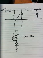
I tend to put a LED in series with the bleeder resistor. This way I get a "free" power indicator (lit=lethal). There still may be voltage across the caps after the LED becomes too dim to see though, so calculating that time constant is still important. I wonder if a CCS might be a better (or faster) option for a bleeder? It would bleed power faster than a resistor as the voltage reduces and keep the LED lit...
EDIT: A LND150 would be about perfect, tie the gate and source together and you have a simple, cheap 1.75ma CCS, which is only slightly higher current draw than a 300v / 220k combo.
EDIT: A LND150 would be about perfect, tie the gate and source together and you have a simple, cheap 1.75ma CCS, which is only slightly higher current draw than a 300v / 220k combo.
Last edited:
I recently bought a factory box of 100 soviet INS-1 dot indicator nixie tubes, since i had a use for like 6 of them, and it was only a few bucks more to get the whole box shipped from Ukraine than to buy half a dozen domestically.
6.5mm diameter tube, 0.5mA at 65v. Pushed through a 1/4" grommet they should make some classy looking hv pilot lights.
.:Sent by pneumatic tubes
6.5mm diameter tube, 0.5mA at 65v. Pushed through a 1/4" grommet they should make some classy looking hv pilot lights.
.:Sent by pneumatic tubes
My question: What is the purpose of the 47k resistor? When I add this in PSUD2, it seems to destabilize the B+.
Thanks!
Probably Thomas is burning 6mA to arrive at the intended B+ voltage.
Inserting a serial resistance to arrive at the same B+ increases the PSU impedance.
Something kind of like this?
Just like that.
Another thing to watch out for with bleeder resistors is that most through-hole resistors are only rated for 300v. It's best to use two or more in series for more headroom. Also, two in series can act as a voltage divider to give you a reference at some nominal value above ground, suitable for providing heater lift if you need it.
- Status
- This old topic is closed. If you want to reopen this topic, contact a moderator using the "Report Post" button.
- Home
- Amplifiers
- Power Supplies
- Understanding power supply