hey guys, i finally got around (and finally got the courage) to build my first cross over
now here comes the question. i have bought all of the parts..but how exactly do i lay them out on the board i will be using? does anyone know of a tutorial on construction that they would like to share with me? any help would be amazing. thanks!
An externally hosted image should be here but it was not working when we last tested it.
now here comes the question. i have bought all of the parts..but how exactly do i lay them out on the board i will be using? does anyone know of a tutorial on construction that they would like to share with me? any help would be amazing. thanks!
 a lil 2 hardcore for my computer speakers (shared w/ family...i'm only 16 ) so ima mount 'em inside the cabinets like always. i just need to know like how to.......pretty much the most prudent and effective way to wire it up while still understanding what i'm doing. like here on the diagram i understand that it goes + - to the coil then + to the cap but then i still have the ends from the cap and the - end of the coil....it'll probably be easier to see when i get them but i'm just wondering if anyone could help me out now. it'll also be the first time i'll veneer my cabinets (my father said
  to bare wood like my 15" dayton and the TMM towers in my room) any tips on veneering as well?
While we can't specifically show you how to lay out the components for your XO, what you can do is to lay them out before you solder, keeping in mind which wires are connected to what and then move them a little closer together untill you have a small enough cluster to fit on a board that will fit your cabinet. A hot glue gun is a wonderful tool. You will find that over the years, your crossovers will get smaller and smaller as your layout techniques get better.
One of the popular things to consider nowadays is that you don't want two coils side by side , both on the flat. You either separate them by at least an inch or more or you alternate between a coil mounted on the flat and a coil mounted on edge. Personally, I haven't gone down that route yet, I just keep the coils apart.
Start this layout on a sheet of paper before transfering to a piece of wood.
Cal
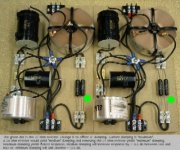
This may or may not help. Shown on this page is a schematic for a crossover and then the completed crossover. Trick to assembling passive crossovers is this I think. Don't focus on the layout of the entire crossover at first, just connect the first two components together, then add the third, then the fourth keeping in mind where the leads to each driver as well as the leads to the "+" and "-" input terminals will go. Don't feel dumb, looking at the schematic and understanding it is pretty easy, sometimes assembling it can take some imagination.
http://www.whatisrazar.com/rearspeakers.html
http://www.whatisrazar.com/rearspeakers.html
Coils have no problem being close, as long as they re not in a parallel (same) direction. When the coils' axis are in a 90 degrees angle there is no interference problem from each other but keeping them in a distance is a good practice.
Btw watch out those crossover calculators! They assume that the drivers behave like resistors, which is wrong and out of reality. Your woofer's impedance is not 8 ohm at 3500 Hz as the crossover calculator thinks.
You shoud use a zobel network to correct the impedance shown to the low pass filter and also make sure that your tweeter has a wide enough 6ohm impedance plateau around 3500hz, otherwise your filters wont cut at 3.5khz.
The zobel calculators themselves dont work well too (same sad story like the filter calculators), but even if they did work well, the online filter calculators do not take into consideration
neither the frequency response of the specific drivers, nor the difraction effects on the frequency response, nor the phase difference which occurs due to the acoustic offset of the drivers when they re mounted on the baffle.
Sorry, i dont want to spoil the fun, but to get it work right you should use a simulation-measuring tool. Otherwise, if using online calculatiors is the only option, do it for a start point, and then try slightly changing the zobel values (at first the zobel, then if necessary try the filter components) to see where it sounds better. On each change you make (one at a time), you should do two listening tests, one with correct tweeter polarity to check the sound quality, and one with the tweeter's polarity reversed to see if you get a deep cancelation at the crossover frequency (using a 3.5khz tone will help much on this ).
When you manage to get a large cancellation in 3.5khz with reversed tweeter polarity, you ll have the best phase matching with correct polarity, thus a clear detailed soundstage. It needs a lot of time on experimenting and/or lots of luck, but it definetly worths the effort.
Good luck.
yeah i appreciate itjomor said:Coils have no problem being close, as long as they re not in a parallel (same) direction. When the coils' axis are in a 90 degrees angle there is no interference problem from each other but keeping them in a distance is a good practice.
Btw watch out those crossover calculators! They assume that the drivers behave like resistors, which is wrong and out of reality. Your woofer's impedance is not 8 ohm at 3500 Hz as the crossover calculator thinks.
You shoud use a zobel network to correct the impedance shown to the low pass filter and also make sure that your tweeter has a wide enough 6ohm impedance plateau around 3500hz, otherwise your filters wont cut at 3.5khz.
The zobel calculators themselves dont work well too (same sad story like the filter calculators), but even if they did work well, the online filter calculators do not take into consideration
neither the frequency response of the specific drivers, nor the difraction effects on the frequency response, nor the phase difference which occurs due to the acoustic offset of the drivers when they re mounted on the baffle.
Sorry, i dont want to spoil the fun, but to get it work right you should use a simulation-measuring tool. Otherwise, if using online calculatiors is the only option, do it for a start point, and then try slightly changing the zobel values (at first the zobel, then if necessary try the filter components) to see where it sounds better. On each change you make (one at a time), you should do two listening tests, one with correct tweeter polarity to check the sound quality, and one with the tweeter's polarity reversed to see if you get a deep cancelation at the crossover frequency (using a 3.5khz tone will help much on this ).
When you manage to get a large cancellation in 3.5khz with reversed tweeter polarity, you ll have the best phase matching with correct polarity, thus a clear detailed soundstage. It needs a lot of time on experimenting and/or lots of luck, but it definetly worths the effort.
Good luck.
. i've never built one before so i guess i have to start somewhere I used an the calc in WinISD for my setup and it works fine with out a zoble. it all depends on what "fine" is For a set of PC speakers you'll be fine, I attend the school of KISS. two speakers with a 1st order set as low as you can. my set up is two wide range speakers, one 2" and one 4" set to cross over at 900 hz, one cap, one foil inductor... done.
But I'm a weird one. I only use odd order XO's, I would spend the time to make a good 3rd long before i would use a 2nd.
But I'm a weird one. I only use odd order XO's, I would spend the time to make a good 3rd long before i would use a 2nd.
Hi lemans23, use this webpage, they show you how to wire your crossover since no one gave you the answer you wanted yet hehe!
http://ccs.exl.info/calc_cr.html

C1 = 3.79 µF
L1 = 0.55 mH
C2 = 2.84 µF
L2 = 0.73 mH
Since it's a crossover for speakers, I hope you got bipolar capacitors. Polarity of components is not important if you got the right thing. You'll only need to wire the free end of the + wire with the free end of the other + wire, then the free end of the - wire with the free end of the - wire, connect to the amplifier and it's done.
http://ccs.exl.info/calc_cr.html
C1 = 3.79 µF
L1 = 0.55 mH
C2 = 2.84 µF
L2 = 0.73 mH
Since it's a crossover for speakers, I hope you got bipolar capacitors. Polarity of components is not important if you got the right thing. You'll only need to wire the free end of the + wire with the free end of the other + wire, then the free end of the - wire with the free end of the - wire, connect to the amplifier and it's done.
simon5 said:Hi lemans23, use this webpage, they show you how to wire your crossover since no one gave you the answer you wanted yet hehe!
http://ccs.exl.info/calc_cr.html
C1 = 3.79 µF
L1 = 0.55 mH
C2 = 2.84 µF
L2 = 0.73 mH
Since it's a crossover for speakers, I hope you got bipolar capacitors. Polarity of components is not important if you got the right thing. You'll only need to wire the free end of the + wire with the free end of the other + wire, then the free end of the - wire with the free end of the - wire, connect to the amplifier and it's done.
i had actually changed the design a lil bit and i found that page soon after i made the initial schematic. could u please go into more detail as to what u mean about the bipolar components?The capacitors you use must be bipolar. That means there's no + or - signs on them, that means the polarity on them is not important.
Usually, if you used electrolytic capacitors, they have a polarity and you must follow the polarity.
Speakers are devices driven by alternative voltage and alternative current. So because the voltage and current is not always positive, you must use components that can work both ways.
It's only a problem with capacitors.
You can use polypropylene, polyesther or oil capacitors (best sound quality).
Cheaper there's Mylar or bipolar electrolytic capacitors (not so good sound quality)
You can't use normal electrolytic capacitors, unless you use two of the same value to build a bipolar electrolytic with it which will have half of capacitance. To do that, you put both + together and you get a bipolar capacitor with no polarity problems.
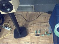
lemans23 said:i finished one of them already. any comments? [/B]
It looks quite good. I would change one of the coils standing up though, even if its not close to the other coil.
To keep the coils ( which are heavy ) in a stable position for ever, except the glue, it is also a good idea to use plastic tie wraps (open two holes on the board next to each coil and use the ties to hold the coils on the board)
simon5 said:The capacitors you use must be bipolar. That means there's no + or - signs on them, that means the polarity on them is not important.
Usually, if you used electrolytic capacitors, they have a polarity and you must follow the polarity.
Speakers are devices driven by alternative voltage and alternative current. So because the voltage and current is not always positive, you must use components that can work both ways.
It's only a problem with capacitors.
You can use polypropylene, polyesther or oil capacitors (best sound quality).
Cheaper there's Mylar or bipolar electrolytic capacitors (not so good sound quality)
You can't use normal electrolytic capacitors, unless you use two of the same value to build a bipolar electrolytic with it which will have half of capacitance. To do that, you put both + together and you get a bipolar capacitor with no polarity problems.
yeah there's no polarity signs on the caps, so i think i'm cool
jomor said:Coils have no problem being close, as long as they re not in a parallel (same) direction. When the coils' axis are in a 90 degrees angle there is no interference problem from each other but keeping them in a distance is a good practice.
Btw watch out those crossover calculators! They assume that the drivers behave like resistors, which is wrong and out of reality. Your woofer's impedance is not 8 ohm at 3500 Hz as the crossover calculator thinks.
You shoud use a zobel network to correct the impedance shown to the low pass filter and also make sure that your tweeter has a wide enough 6ohm impedance plateau around 3500hz, otherwise your filters wont cut at 3.5khz.
The zobel calculators themselves dont work well too (same sad story like the filter calculators), but even if they did work well, the online filter calculators do not take into consideration
neither the frequency response of the specific drivers, nor the difraction effects on the frequency response, nor the phase difference which occurs due to the acoustic offset of the drivers when they re mounted on the baffle.
Sorry, i dont want to spoil the fun, but to get it work right you should use a simulation-measuring tool. Otherwise, if using online calculatiors is the only option, do it for a start point, and then try slightly changing the zobel values (at first the zobel, then if necessary try the filter components) to see where it sounds better. On each change you make (one at a time), you should do two listening tests, one with correct tweeter polarity to check the sound quality, and one with the tweeter's polarity reversed to see if you get a deep cancelation at the crossover frequency (using a 3.5khz tone will help much on this ).
When you manage to get a large cancellation in 3.5khz with reversed tweeter polarity, you ll have the best phase matching with correct polarity, thus a clear detailed soundstage. It needs a lot of time on experimenting and/or lots of luck, but it definetly worths the effort.
Good luck.
Passives are infinitely annoying....
i find it beautiful like a mangy dogCal Weldon said:Are you sure you couldn't make that XO any uglier?
btw i finished the other 2day and will start planning the cabinets while i'm going to sleep (don't ask
 )
)
- Status
- This old topic is closed. If you want to reopen this topic, contact a moderator using the "Report Post" button.
- Home
- Loudspeakers
- Multi-Way
- ultra newcomer crossover question