Hello All,
Can someone with more experience assist with these two questions please?
I understand the need for inrush current limiting on the primary side of a toroidal transformer when >=500VA. It can be achieved in many ways, although I've chosen to go with some series resistors and a relay that bypasses them after around 200ms. The first question is what is happening on the secondary in terms of current and voltage during the 200ms inrush phase?
I've read on the forum about reservoir capacitor slow charge, for when the total uF on each power amp rail is high and when discharged the capacitors provide a short circuit to the transformer secondary. Slowing the charge rate to under the max ripple current capacity can be achieved again, by a resistor that is bypassed by a relay. The second question is I can't find people on the forum actually using capacitor slow charge, therefore, is this essentially achieved by the primary side inrush current limiting or a separate problem?
Thanks,
Ian
I can't speak for other people, but my own preference is to let the soft-start also have the (desirable) side effect of limiting peak current that charges the big filter capacitors. So I don't short out the current-limiting resistive device (an Ametherm ICL) until after 20-30 half cycles of the mains AC have arrived (330msec - 600msec). This charges up the filter capacitors a pretty good amount, so that when the shorting relay engages, the charging current is a lot less than it otherwise would be. I also like to use 50 amp rectifiers rated for 450 amps peak surge, so the final charge-up doesn't stress anything except perhaps fast-blow fuses.
Last edited:
This is actually quite a topic you have here.In the classic transformer/diode bridge/capacitor setup you must deal with 3 different phenomenae.
1) transformer remanent magnetisation
2) Power grid phase angle at the moment of turn-on
3) capacitor charge current
All these phenomena can be combatted by means of for example a relais bridged resistor or a NTC.
But there is number #3 in the list.. and there is the caveat. Let me explain :
The charge in the capactor(s) in fully charged state is 1/2*CVV expressed in Joules.If you try to charge an empty capacitor from a voltage source with a resistor isn series, the voltage source will deliver CVV joules and the resistor will dissipate half this energy being 1/2*CVV(Joules).The other half will end up as charge in the capacitor.
So what happens if you charge the capacitor without a resistor?? The answer is :you cannot ,there is always resistance -> capacitor ESR ,winding resistance in your transformer,wiring resistance of your home grid up until resistances in the whole power generation chain the nation-wide-grid.
So when you charge up a capacitor without a resistor in series, the 1/2*CVV power will be divided over a lot of elements, most of them beyond the scope of your view and all of them big and bulky.
The highest of these resistances will get the most power=energy to swallow.
Now as soon as you put a resistor in series of let’s say 10 Ohms ,this one will be the highest resistance in the whole chain and take all the heat!
As soon as you start messing with this series resistance you will have to deal with all of it, and it largely depends on the amount of capacitance you have behind your bridge.
The positive side of this can be a whole lot of good too ,as Mark Johnson said : it will limit the stress on your rectifiers, you can put a much lower value (fast tripping) fuse in the primary and even eliminate fuses in the secondary without compromising safety.
The Ametherm inrush current limiters (ICL) are actually made for this purpose and they can take about 250Joules of energy e.g. max 100,000uF @50V, but they will get hot permanently.
If you don’t like all this heat being wasted ,you may opt for a relay contact bridging the ICL.
This is in fact also better for the case of someone powering down the amp and immediately powering it up again (or short power interruption) The NTC will be cold ant his have a high resistance in contrast to the situation without a relay.
Standard power resistors are often not specced nor suitable for a short term overload situation such as described above and have to be carefully chosen
I prefer to separate soft start from slow charging.
For soft start I use a close rated fuse to suit the transformer, eg. 500VA on 230Vac uses a T2A fuse.
That fuse needs a current limiting resistor.
I switch out that resistor with a small mains rated relay after ~150 to 200ms.
I typically use +-20mF for each amplifier channel.
My latest uses +-45mF to feed two 8ohms channels.
It is fed from a 300VA 230Vac transformer started with an 80r current limiting resistor that switches out after ~200ms. The T1.6A mains fuse never ruptures.
The slow charging effect has been achieved by the resistances mentioned by Cowboy.
I don't know how big the smoothing capacitor bank would need to be to rupture the soft starting close rated fuse.
But, finally, whatever type of current limiting device/s you adopt, always bypass it/them to minimise the source impedance of the PSU.
PSU performance depends on low source impedance.
Thank you everyone for your contributions, much appreciated.
So the consensus of opinion is to place inrush current limiting on the AC side by either a relay bypassed resistor or NTC and nothing additionally on the DC side.
For reference the 500VA 0-30 0-30 toroidal transformer (two bridge rectifiers) will be feeding four mono amplifiers rated at around 90W each. Each rail will have capacitance of 9400uF, so that's 37600uF in total per rail.
I'm wrongly or rightly concerned about the heating effect of the capacitors because the amp will be used on demand as opposed to on for long periods of time. Can I make sure the caps aren't charged with more current than their rated maximum ripple current? If that's an issue can it be mitigated by a larger resistor in the primary or by bypassing that resistor after say (guessing) 500ms instead of around 200ms?
NTC's from reading seem better used on 110v whereas I'm using 240v? Alternatively for resistors am I better with just one high power or several lower power in series?
If I can I try to avoid slow start circuits.
Its extra circuitry you can hopefully do with out and relays eventually wear out.
If I am using 10,000uF per rail then I don't bother with a slow start circuit.
I hate relays so usually use a PIC micro with a triac and raise up the phase angle slowly.
Its extra circuitry you can hopefully do with out and relays eventually wear out.
If I am using 10,000uF per rail then I don't bother with a slow start circuit.
I hate relays so usually use a PIC micro with a triac and raise up the phase angle slowly.
Hi Ians, Your caps will have to be charged up till 42V, an will hold approx 36Joules of energy in total. So that's the rating you will minimally need for an NTC, take some extra because the tranny will also need some energy before it's nicely balanced magnetically.
Furthermore ,it is well known that surges happen frequently (from distant lightning strikes and heavy machinery on the grid) they will also kick you NTC.
IEC61000-4-5 discribes a test method for apparatus ,might you be interested. I conducted many of hese tests, and frequently a too small NTC explodes at 2kV surges.Fuses also happen to open due to the high current.
Nigel,
Your method with a triac sounds interesting as it presumably is better than a bypassed resistor or NTC? It still offers slow charge by virtue of it limiting primary current? However, having read a few things on the forum about triacs I'm of mixed opinion. Do they not either allow or generate DC which toroidal transformers don't like and surely it will also require a heatsink of its own? Noting Andrew's advice I think I would want to bypass it with a relay, that removes heat(?) even if relays don't live forever.
Cowboy,
The NTC route makes me a little nervous as I can't carry out any testing but I'd again want to bypass it for safety if this is really better than an resistor.
The triac will need a heat sink.
Size depends on how much power it uses.
The triac is switched at the same point on +ve and -ve cycle so there is no DC.
If you want the PIC code let me know.
Size depends on how much power it uses.
The triac is switched at the same point on +ve and -ve cycle so there is no DC.
If you want the PIC code let me know.
An externally hosted image should be here but it was not working when we last tested it.
Last edited:
Does a Triac operate like a switch, i.e. it is OFF, or it is ON.
Yes it is on or off.
You later the phase angle to adjust how much power is applied to the load.
That is not a nice way to start a transformer.
The emi emitted during the triac switching is enormous.
A soft start operates very differently and uses a resistance as a current limiter.
A slow charge as described by the Power NTC manufacturers, also uses a resistance as a current limiter.
The emi emitted during the triac switching is enormous.
A soft start operates very differently and uses a resistance as a current limiter.
A slow charge as described by the Power NTC manufacturers, also uses a resistance as a current limiter.
Yet lots of people do it exactly this way.That is not a nice way to start a transformer.
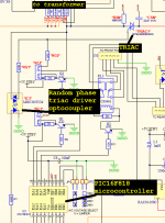
Sufficiently motivated readers will be able to find Bryston's web page where they present the circuit schematics of their amplifier products, just as I have. On that page you will find a PDF schematic of the Bryston 2BSST amplifier, which I have excerpted in Fig.1 below.
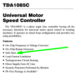
You'll see there is a PIC microcontroller chip, which controls the transformer soft start using a triac and a triac gate-driver + optocoupler. Previous generations of Bryston power amps used a TDA1085C chip + triac for soft start; later they dropped that chip and programmed their own soft start algorithm into an inexpensive uC. Saved themselves some money and got exactly the soft start they wanted, at the same time. Schematics for those older generation amps are also provided on Bryston's download page.
_
Attachments
Yes the triac is a near-ideal switch, and obviously when you switch it "ON" you connect the mains directly to the transformer primary. This is not a deep insight.The first time the triac closes the mains is directly connected to the transformer.
The deep insight is, because the mains waveform is a leisurely 60 Hz, you can precisely control the exact instant when you close (and open) the switch.
The people who designed the TDA1085C integrated circuit in post#14 above, had this deep insight. They realized that the sinusoidal voltage across an ideal inductor, leads the sinusoidal current by pi/2 radians. They also measured lots of physical, non-ideal, inductive loads like motors, transformers, solenoids, etc., and found the range of E-vs-I phase relationships observed in practice.
Knowing this, the job is now to throw the switch (change the triac from Hi-Z to Lo-Z) at exactly the right sinusoidal voltage, such that the sinusoidal current is zero. Presto, there's no discontinuity in current.
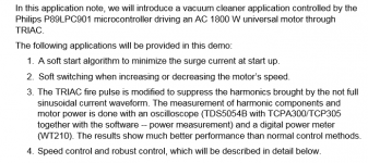
This is all discussed very nicely in the Philips' (now NXP's) application note AN10496, which I have excerpted below. They manage to control exactly when their IC switches the triac, to achieve soft start of a 1800 Watt AC motor. Which makes our puny 750VA audio power supply transformers, appear feeble and impotent.
Although I'm sure that Bryston employs more than one person with a graduate degree in electrical engineering, who can derive the optimum switching points using nothing but EE theory, pencil, and paper --- this is not the only way to skin the cat. Unschooled copyists can achieve the same thing merely by purchasing a few TDA1085C chips, building up the circuits shown in the datasheet figures, and then capturing the resulting waveforms on a storage oscilloscope. Do the same for the Philips/NXP P89LPC901 and capture its waveforms too. Now write software for your PIC microcontroller that emits these very same waveforms. Presto, job done, without a single lick of EE theory. {you do, however, assume that Toshiba and Philips are shipping good parts that work well in real life, i.e., the fundamental axiom of copycat profits}
EE's: remember that dreary old mnemonic ELI the Ice Man? Here's an application of it in real life! Woohoo, professor Krishnamurthy was finally right about something.
If you're wondering how on earth I found that Philips application note, the answer is disappointingly prosaic: DuckDuckGo web search for pages containing the three words
- triac soft start
_
Attachments
Hi,
To Mark Johnson:
That it is the way I do it as you explained. By using a micro you can easily prevent the inrush current by slowly bringing the AC voltage up/down. I used the zero crossing to synchronize the firing of the triac at the right angle of the AC sine wave. By doing so I can ramped up/down the AC on power ON/OFF. Doingso it will minimizes the inrush current and also will bring slowly the AC Up or Down. I used a solid state relay without the zero crossing option. It is a simple circuit since most of the control it is done in the programming. Right now I am using the Zbasic micro but I am looking forward to implement it in the Arduino UNO. Also once the AC it is turned ON the triac it is bypassed since the triac it is continuously tuning ON/OFF at zero crossing.
I'll try to remember to quote this statement, when you lecture people about "AC stuff" and are wrong.I am not good at this AC stuff.
There's a saying in the USA about a specific type of tiresome person: "Often wrong, but never in doubt".
The saying will spring to mind when, in future, I read erroneous lectures about "AC stuff". Especially stubborn, wrong-headed, obviously incorrect lectures. A good link to keep handy: we shall see.
- Status
- This old topic is closed. If you want to reopen this topic, contact a moderator using the "Report Post" button.
- Home
- Amplifiers
- Power Supplies
- Toroidal Transformer Inrush & Capacitor Slow Charge