Toroidal Coils actually have a very illustrious history:
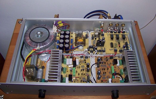
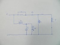
Here used in a power supply. The thing top left.
This is what we call a transformer, or more accurately, an impedance converter. 250V AC being converted down to about 50V by what we know as a turns ratio, then rectified into DC by a diode bridge.
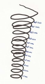
The theory says that toroidal coils have far less interaction than a straight line coil like the thing at the top:
Actually, we can apply the theory of right-angles, more mathematically known as "Orthogonality" to keep interaction apart. This is all well and good with 3 coils, in a 3D Universe.
After that, you are on your own.
Here used in a power supply. The thing top left.
This is what we call a transformer, or more accurately, an impedance converter. 250V AC being converted down to about 50V by what we know as a turns ratio, then rectified into DC by a diode bridge.
The theory says that toroidal coils have far less interaction than a straight line coil like the thing at the top:
Actually, we can apply the theory of right-angles, more mathematically known as "Orthogonality" to keep interaction apart. This is all well and good with 3 coils, in a 3D Universe.
After that, you are on your own.
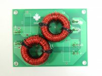
I would like to know your opinions when using toroid inductors for speaker crossover. The board and toroid inductors are made by me here in Canada.
What's the core material? In my limited experience of creating inductors for XOs, I needed an air gap when using ferrite to get the target inductance with manageable diameter wire. I know that toroids exist which have air gaps but haven't any experience with them.
This is the direction I am heading for my own XO. Air Toroid. A toroidal geometry eliminates cross-talk. In other terms. Std wound cores have their magnetic center shooting out from the center which forces one to heavily consider their mounting position, similar to tube amp's OT. With a toroid that is not a problem, so it just makes sense. If there is room, use it for the woofer as well. While it is bulky and larger, I think there is a great benefit in using air cores all the way. Perhaps not necessary but its the small details that count.
...I would like to know your opinions when using toroid inductors for speaker crossover...
Have you made any measurements telling you the saturation current?
Do you mean that we can't place a 4th coil in the 4th dimension?This is all well and good with 3 coils, in a 3D Universe. After that, you are on your own.
Attachments
This is the direction I am heading for my own XO. Air Toroid. A toroidal geometry eliminates cross-talk. In other terms. Std wound cores have their magnetic center shooting out from the center which forces one to heavily consider their mounting position, similar to tube amp's OT. With a toroid that is not a problem, so it just makes sense. If there is room, use it for the woofer as well. While it is bulky and larger, I think there is a great benefit in using air cores all the way. Perhaps not necessary but its the small details that count.
Not to be snarky, but an air core toroid is probably a nonsequitur, or at least wildly inefficient. The magnetically permeable core is the only thing that allows you to bend the coil into a circle (and also concentrates the magnetic field in that loop so as to not interact much with nearby objects)
Air gap and air core are certainly two very different things
Avoiding saturation would be my greatest concern, and I too have no experience with air-gapped toroids. Are such things even widely available?
That's a really pretty board. Is that about the same inductance for both crossover sections, though? Usually it doesn't work out that way, with the difference in input and output impedance.
Just curious.
Regards, Rick
Last edited:
Not to be snarky, but an air core toroid is probably a nonsequitur, or at least wildly inefficient. The magnetically permeable core is the only thing that allows you to bend the coil into a circle (and also concentrates the magnetic field in that loop so as to not interact much with nearby objects)
Air cored toroids certainly exist - take a look down this table of core materials. Right down at the bottom is material -0 which has a mu of 1. I.e. its just a former with no magnetic properties at all.
Material Characteristics
I haven't made any measurement of saturation current of the inductor. One of our engineers will help measuring the saturation current of the inductor next week.Have you made any measurements telling you the saturation current?
Is that about the same inductance for both crossover sections, though? Usually it doesn't work out that way, with the difference in input and output impedance.
Hi Rick,
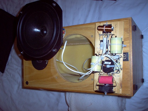
I use exactly same inductors (inductance and DC resistance) and same capacitors for both crossover sections. I would like to know if it works when woofer and tweeter have the same impedance (8 Ohm). I recently have replaced a crossover network of one two way speaker with this crossover network. I like the sound of speaker with new crossover network. That is the sound i am looking for (for more than 30 years). I have the idea because i don't like the sound of the speaker with original crossover network.
Attachments
Hi tuantran,
Theory certainly matters a lot more to some of us than others! (And yes, I'm too often guilty of diving in where its too deep for my own good.)
But hey -- if you got the sound you want, finally(!) after chasing it for 30 years (!!) -- you might just save studying the theory for another project ...
The one bit of it that deserves mention, though: A few too many of the formula are calculated for matching impedance in and out. They ignore the component value changes necessary when the music is coming from a very stiff voltage source.
Still, glad you're happy with it,
Rick
Theory certainly matters a lot more to some of us than others!
(And yes, I'm too often guilty of diving in where its too deep for my own good.) But hey -- if you got the sound you want, finally(!) after chasing it for 30 years (!!) -- you might just save studying the theory for another project ...
The one bit of it that deserves mention, though: A few too many of the formula are calculated for matching impedance in and out. They ignore the component value changes necessary when the music is coming from a very stiff voltage source.
Still, glad you're happy with it,
Rick
Last edited:
- Status
- This old topic is closed. If you want to reopen this topic, contact a moderator using the "Report Post" button.
- Home
- Loudspeakers
- Multi-Way
- Toroid inductors for speaker crossover