Its amazing how a persons (mine anyway) thinking can do a complete 180. When I decided to re-pursue my audio interests after almost 2 decades, I brought with me the baggage of the 80’s. Specifically “The more power the better” line of thinking that went along with the efficiency of the better speakers of the era (my favorite speakers were the Celestion SL6’s and anything from the Apogee ribbon line, in the low 80’s in efficiency all ). Knowing that I eventually wanted to play around with some diy ribbons, I figured that if I was to do SE, I would have to go BIG with an 813 or two.
That all changed when I came across this thread…
http://www.diyaudio.com/forums/showthread.php?s=&threadid=50162
Bottom line, with the availability of extremely powerful “Rare Earth” magnets, ribbons in the 96-106 dB range can and have been made. Using the info and software mentioned in the thread, I have come up with a dual 36”x .75” design with a projected efficiency of 106dB@ 1W. I soon realized that 4 Watts behind this kind of efficiency is comparable too more than 400 Watts driving Apogee’s… I’ll take it .
Being a firm believer in the “simple as it can be” school of thought, I was really intrigued with the “spud” amps, particularly Brian Clark’s “el Spuddo” and Stefano Perugini’s “ST” amps. These guys really inspired me.
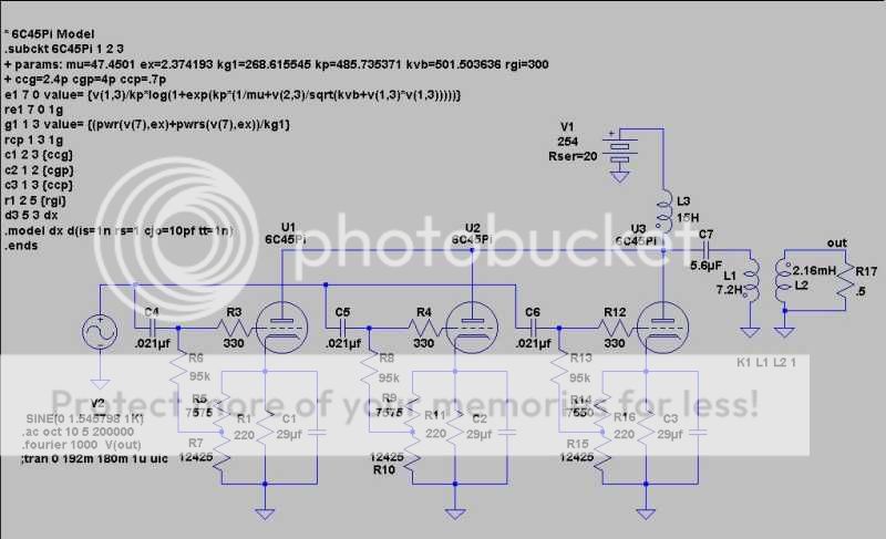
Without further ado, I give you the ” ‘Tater Patch”…
To be clear I have not made this amp yet, and I hope the collective wisdom here can point out any errors.
I intend to run my ribbons down to 100hz, so I need a sharp rolloff. The amp does double duty as a quasi 4th order highpass filter. By jiggering the coupling and de-coupling cap values I was able to get a progressively sharper rolloff with a 3db down point of 100 hz . As a bonus, this reduced the value of the cathode by-pass caps to the point that I don’t have to use electrolytic…beauty.
Simulating in LtSpice at 1 Watt gives this distortion breakdown…
Harmonic Frequency Fourier Normalized Phase Normalized
Number [Hz] Component Component [degree] Phase [deg]
1 1.000e+03 4.987e-01 1.000e+00 8.27° 0.00°
2 2.000e+03 2.681e-03 5.376e-03 -77.40° -85.67°
3 3.000e+03 1.095e-04 2.195e-04 17.35° 9.08°
4 4.000e+03 1.330e-05 2.667e-05 -156.88° -165.15°
5 5.000e+03 1.200e-05 2.407e-05 -140.97° -149.24°
6 6.000e+03 1.068e-05 2.142e-05 -135.54° -143.81°
7 7.000e+03 9.912e-06 1.988e-05 -131.01° -139.29°
8 8.000e+03 9.382e-06 1.881e-05 -127.15° -135.42°
9 9.000e+03 8.997e-06 1.804e-05 -123.80° -132.07°
Total Harmonic Distortion: 0.538053%
And at 4 Watts…
Harmonic Frequency Fourier Normalized Phase Normalized
Number [Hz] Component Component [degree] Phase [deg]
1 1.000e+03 9.951e-01 1.000e+00 8.32° 0.00°
2 2.000e+03 1.085e-02 1.090e-02 -76.94° -85.27°
3 3.000e+03 1.011e-03 1.016e-03 17.97° 9.64°
4 4.000e+03 2.964e-05 2.978e-05 139.86° 131.54°
5 5.000e+03 2.455e-05 2.467e-05 -123.78° -132.10°
6 6.000e+03 1.927e-05 1.936e-05 -111.98° -120.30°
7 7.000e+03 1.869e-05 1.878e-05 -108.80° -117.12°
8 8.000e+03 1.853e-05 1.862e-05 -106.48° -114.80°
9 9.000e+03 1.835e-05 1.844e-05 -104.44° -112.76°
Total Harmonic Distortion: 1.094966%
The 1Watt FFT , and the 4 Watt FFT show a nice harmonic progression that’s mostly second order.
As shown, the the tubes are running with 240V at the plates, -3.1V at the grids, and at 37.25mA .
Iv’e attached the Ltspice .asy file along with the files for the output transformer for Yvesm’s OPT Assistant in case anybody wants to play with them.
Ok, be brutal…let me know if/were I’m screwing up here, as well as any suggestions to improve on it.
Thanx,
Casey
That all changed when I came across this thread…
http://www.diyaudio.com/forums/showthread.php?s=&threadid=50162
Bottom line, with the availability of extremely powerful “Rare Earth” magnets, ribbons in the 96-106 dB range can and have been made. Using the info and software mentioned in the thread, I have come up with a dual 36”x .75” design with a projected efficiency of 106dB@ 1W. I soon realized that 4 Watts behind this kind of efficiency is comparable too more than 400 Watts driving Apogee’s… I’ll take it .
Being a firm believer in the “simple as it can be” school of thought, I was really intrigued with the “spud” amps, particularly Brian Clark’s “el Spuddo” and Stefano Perugini’s “ST” amps. These guys really inspired me.
Without further ado, I give you the ” ‘Tater Patch”…
To be clear I have not made this amp yet, and I hope the collective wisdom here can point out any errors.
I intend to run my ribbons down to 100hz, so I need a sharp rolloff. The amp does double duty as a quasi 4th order highpass filter. By jiggering the coupling and de-coupling cap values I was able to get a progressively sharper rolloff with a 3db down point of 100 hz . As a bonus, this reduced the value of the cathode by-pass caps to the point that I don’t have to use electrolytic…beauty.
Simulating in LtSpice at 1 Watt gives this distortion breakdown…
Harmonic Frequency Fourier Normalized Phase Normalized
Number [Hz] Component Component [degree] Phase [deg]
1 1.000e+03 4.987e-01 1.000e+00 8.27° 0.00°
2 2.000e+03 2.681e-03 5.376e-03 -77.40° -85.67°
3 3.000e+03 1.095e-04 2.195e-04 17.35° 9.08°
4 4.000e+03 1.330e-05 2.667e-05 -156.88° -165.15°
5 5.000e+03 1.200e-05 2.407e-05 -140.97° -149.24°
6 6.000e+03 1.068e-05 2.142e-05 -135.54° -143.81°
7 7.000e+03 9.912e-06 1.988e-05 -131.01° -139.29°
8 8.000e+03 9.382e-06 1.881e-05 -127.15° -135.42°
9 9.000e+03 8.997e-06 1.804e-05 -123.80° -132.07°
Total Harmonic Distortion: 0.538053%
And at 4 Watts…
Harmonic Frequency Fourier Normalized Phase Normalized
Number [Hz] Component Component [degree] Phase [deg]
1 1.000e+03 9.951e-01 1.000e+00 8.32° 0.00°
2 2.000e+03 1.085e-02 1.090e-02 -76.94° -85.27°
3 3.000e+03 1.011e-03 1.016e-03 17.97° 9.64°
4 4.000e+03 2.964e-05 2.978e-05 139.86° 131.54°
5 5.000e+03 2.455e-05 2.467e-05 -123.78° -132.10°
6 6.000e+03 1.927e-05 1.936e-05 -111.98° -120.30°
7 7.000e+03 1.869e-05 1.878e-05 -108.80° -117.12°
8 8.000e+03 1.853e-05 1.862e-05 -106.48° -114.80°
9 9.000e+03 1.835e-05 1.844e-05 -104.44° -112.76°
Total Harmonic Distortion: 1.094966%
The 1Watt FFT , and the 4 Watt FFT show a nice harmonic progression that’s mostly second order.
As shown, the the tubes are running with 240V at the plates, -3.1V at the grids, and at 37.25mA .
Iv’e attached the Ltspice .asy file along with the files for the output transformer for Yvesm’s OPT Assistant in case anybody wants to play with them.
Ok, be brutal…let me know if/were I’m screwing up here, as well as any suggestions to improve on it.
Thanx,
Casey
Attachments
Oopsie...reviewing my post, I see the most imprtant part, the questions , didn't make it in (it was late and I was copying from Word).
Anyhoo..First, this is my first spice simulated design, actually it’s my first spice anything. Just how accurate is spice at predicting "real world" performance? I suspect it boils down to the accuracy of the tube model.
Second...I want to be able to swing the B+ from 150-260 so that I can find the operating point that best suits my ageing ears. The resistors in parallel of the cathode resistor will be a 20k pot so I can accommodate any bias needs. What approach would you guys recommend ? I’m thinking a dedicated variac, or, a series regulator. As this is intended for very efficient speakers, and has no feedback above 25hz, low ripple is a must. Any suggestions as to just how low I should shoot for ? I’m just starting the supply design, and want to make sure I’ve got a usable target.
Third…The ribbon that this will be driving will have NO tolerance for the low frequency swings that occur during turn on. I’m thinking a relay protection circuit. Is a simple delay the best way to go, or should I consider some sort of monitor circuit that closes the relay after it settles ?
Thanx guys,
Casey
> Ok, be brutal. . .
OK.
> -3.1V at the grids,
So why drop 8.25V in the 220 ohm cathode resistors? It isn't improving bias stability. Seems like six extra parts.
Why have three separate grid coupling R-C networks? One should do for the whole trio.
> a firm believer in the “simple as it can be” school of thought
I've just chopped ten parts out, and I say it will work the same. What am I missing? Oh . . . .
> I want to be able to swing the B+ from 150-260 so that I can find the operating point that best suits my ageing ears....What approach would you guys recommend?
Unless you like the sound of clipping, the highest voltage the tubes will stand. Why would a "starved" amp sound better? (Let's see what kind of debate that remark stirs-up!)
> I was able to get a progressively sharper rolloff with a 3db down point of 100 hz
For the first decade, it is only 6dB/octave, pretty tame for reducing bass-slap. If you get clever with C7 L1, you can get a self resonance around 100Hz. Scale the R/L ratio for a Q-bump about 3dB at 100Hz, then shorten the grid R-C network so it is 3dB down at 100Hz; you get flat to 100Hz and 18dB/oct below that. THAT will keep the bass (and much of your start-up thump) out of the floppy ribbon. And incidentally, leads to cheaper parts: like 1uFd and 4H. Do some more fiddles to get your desired slope 50Hz-100Hz.
And to sprinkle cold water on your basic plan....
> a projected efficiency of 106dB@ 1W.
At what distance? IIRC, an omni-directional source of 1 Acoustic Watt gives 108dB SPL at 1 meter. If the ribbon were an omni radiator (it is not), then that would suggest an electro-acoustic conversion efficiency of 63%. That's unlikely. If it happened, the electric impedance would rise far above the ribbon resistance. When you see that, it is a good sign, but you'll have to re-match your amplifier.
And there are Rules Of Nature that won't be violated. Your diaphragm area is like a 8"-10" circle. Eights and tens don't give broadband efficiency starting at 100Hz much higher than 2%. 0.02 Acoustic Watts from an omni radiator is 91dB SPL at 1 meter.
The ribbon is hardly omni. That does not improve its efficiency bandwidth. It does throw sound more in some directions than others. But a 72" tall line source will only have about 6dB directivity at 100Hz. So maybe 97dB SPL/Watt at 1 meter. That's flippin' fantastic, and is possible only because super-magnets have become cheap. It is still 9dB short of where you seem to think you will get. I'd be interested to learn that a 100Hz 106dB SPL @1m ribbon is possible... it seems unlikely to me.
Another reason it seems unlikely: an efficiency, clarity, and cost ratio like that in a stackable system would be KILLER for large-room sound systems. Yes, there are some PA ribbons, but if they were that good they would have driven-out voice-coil systems by now.
(Let's see what kind of debate that remark stirs-up!)
So good to me !
Put 400v at the plate of a good ole 6L6, with 250v screen and 6K load rather than the 250 250 4K2 as suggested in the data sheet.
It's another toob !
Yves
Hi there....................round up component values to what is actually on the market....The values C7 L1.......C7 seems very low and won't effectively damp LS at 100Hz.
Have you calculated the resonant frequency arising from the leakage inductance of LI/L2 with C7 ? Check that it doesn't sit right in the audio band.
richj
Have you calculated the resonant frequency arising from the leakage inductance of LI/L2 with C7 ? Check that it doesn't sit right in the audio band.
richj
Hello PRR
The resistors in parallel with the cathode resistors represent a 20k pot. This gives me the flexibility to match the tubes operating points, it also provides for changing this point around.
Agreed..however, I noticed during simulation that the tubes see-saw, ie, when I lower the bias of one, the other two go up when set up with a common R-C. In fact, when you cut one out (think loosing a filament) the other two started dissipating around 20 Watts each…not good.
See above
Well I don’t want to clip the amp, I figure my max volume will have to go down with the B+. As far as “starving” goes, in its current configuration I’m technically “over-feeding” it as it has an official Vmax of 150V. I suspect I’ll end up were it is, I just want to be able to confirm were it is, is “right”.
Look closer (I know, it’s a junky screen grab), the curve is progressive, its down 9db at 50hz and ends up at 24dB per octave around 25hz. I chose the gentle initial slope so as to not throw the phase to far out at the x-over point. It’s -75deg. At 100hz. It’s a balancing act to be sure, and I may have to change it.
Hmm…I’ll have to play with that…interesting idea.
I won’t point by point your justified skeptisim on the ribbon, instead read the thread I pointed too. I will point out though , that I’m talking about 2) .75 x 36” ribbons side by side in a common frame, you can see the drawing of the magnet assembly here . Using the same software and formulas that predicted the performance of the ribbon described in the thread to within 1dB of actual performance, my design comes out to 103dB@ 1 Watt @ 1 meter with 10 micron foil, and 106dB with 5 micron foil. I’m still not convinced I’ll reach this, which is why I’m building a ‘Tater Patch of 4 Watts instead of a simpler Spud amp with 1.
Uhh..no. These ribbons can’t handle the power needed, even at these efficiencies. Not to mention you can tear one by blowing on it hard.
Later,
Casey
So why drop 8.25V in the 220 ohm cathode resistors? It isn't improving bias stability. Seems like six extra parts.
The resistors in parallel with the cathode resistors represent a 20k pot. This gives me the flexibility to match the tubes operating points, it also provides for changing this point around.
Why have three separate grid coupling R-C networks? One should do for the whole trio.
Agreed..however, I noticed during simulation that the tubes see-saw, ie, when I lower the bias of one, the other two go up when set up with a common R-C. In fact, when you cut one out (think loosing a filament) the other two started dissipating around 20 Watts each…not good.
I've just chopped ten parts out, and I say it will work the same. What am I missing?
See above
Unless you like the sound of clipping, the highest voltage the tubes will stand. Why would a "starved" amp sound better? (Let's see what kind of debate that remark stirs-up!)
Well I don’t want to clip the amp, I figure my max volume will have to go down with the B+. As far as “starving” goes, in its current configuration I’m technically “over-feeding” it as it has an official Vmax of 150V. I suspect I’ll end up were it is, I just want to be able to confirm were it is, is “right”.
For the first decade, it is only 6dB/octave, pretty tame for reducing bass-slap
Look closer (I know, it’s a junky screen grab), the curve is progressive, its down 9db at 50hz and ends up at 24dB per octave around 25hz. I chose the gentle initial slope so as to not throw the phase to far out at the x-over point. It’s -75deg. At 100hz. It’s a balancing act to be sure, and I may have to change it.
Scale the R/L ratio for a Q-bump about 3dB at 100Hz, then shorten the grid R-C network so it is 3dB down at 100Hz; you get flat to 100Hz and 18dB/oct below that.
Hmm…I’ll have to play with that…interesting idea.
And to sprinkle cold water on your basic plan....
I won’t point by point your justified skeptisim on the ribbon, instead read the thread I pointed too. I will point out though , that I’m talking about 2) .75 x 36” ribbons side by side in a common frame, you can see the drawing of the magnet assembly here . Using the same software and formulas that predicted the performance of the ribbon described in the thread to within 1dB of actual performance, my design comes out to 103dB@ 1 Watt @ 1 meter with 10 micron foil, and 106dB with 5 micron foil. I’m still not convinced I’ll reach this, which is why I’m building a ‘Tater Patch of 4 Watts instead of a simpler Spud amp with 1.
Another reason it seems unlikely: an efficiency, clarity, and cost ratio like that in a stackable system would be KILLER for large-room sound systems. Yes, there are some PA ribbons, but if they were that good they would have driven-out voice-coil systems by now.
Uhh..no. These ribbons can’t handle the power needed, even at these efficiencies. Not to mention you can tear one by blowing on it hard.
Later,
Casey
You refute my amp comments well. It does not suit me but it may suit you fine.
Input capacitance should be a non-issue.
> read the thread I pointed to
Every post, though not every word.
I am astounded that you can get 5,000-10,000 Gauss across a 1/2" or even 3/4" gap, a yard long, with chump-change magnets. The Old Men, who moved from electromagnets to Alnico, would think they died and went to heaven. It allows transducer designs that were simply impossible before.
Otherwise: grandpa knows how to suck eggs. Air is air, aluminum is still aluminum.
A couple times in that thread, a concise list of equations for efficiency and sensitivity were posted. They seem to take no account of air loading. This is an acceptable assumption for the original treble-only drivers. It can't be neglected at 100Hz on a 36"x0.75" radiator. Some of the broadband curves show a bass-slump, typically 3dB/octave (though sometimes masked by resonances or inadequate baffling).
I'll have to skim Olson again. Combining the diaphragm and conductor leads to about 6dB better efficiency than a coil-cone layout. Distributed drive might allow lower mass/area ratios (or might open-up all sorts of resonances). But there are still some fundamental relations between mouth area and bass efficiency, that don't depend on electrodynamic factors. (The intersection of the acoustic limit and the electromechanical factor sets the bass corner.) A 130 square inch radiator can just about get 8% efficiency at 150Hz, about 97dB SPL at 1m. When you lose acoustic loading, radiation efficiency tumbles AND driver impedance rises due to back EMF.
27 square inches into a horn would do OK to 100Hz, especially in the home. But a 100Hz horn needs a mouth over 600 square inches. With 27sqin throat, that's a yard long. It starts to (sorta) resemble a PA horn, which will do 108dB SPL at 1m, but is bulky and heavy and not wide dispersion.
There IS a whole bag of tricks for improving bass radiation efficiency. Thought-provoking. The very large aspect ratio is foiling my approximations, I have to go back to books.
> These ribbons can’t handle the power needed, even at these efficiencies. Not to mention you can tear one by blowing on it hard.
PA horn driver diaphragms are made of similar aluminum foil, though hardened and pressed into a dome. These are indeed easy to damage by handling. But driven properly they deliver 10 acoustic (not electric) watts all night long.
Ribbon microphone diaphragms are an order of magnitude thinner. Yes, they do get damaged by wind-gusts, but not as often as you'd think.
The resistors in parallel with the cathode resistors represent a 20k pot. This gives me the flexibility to match the tubes operating points, it also provides for changing this point around.
It's a good idea to stick to this plan because of the very wide variations in the specs of these hot tubes. The whole idea seems a redundancy but it's really a good way to handle 6C45p's. This is DIY after all and "engineering economy" is no issue.
John
EC8010 said:The input capacitance of your proposed amplifier will be rather large to say the least...
I guess roughly 350-450pF.
distortion figures using LTSpice
Valveitude :
Your tube model is using Koren's equations, and I have found it to be pretty good, so your tube model probably should be OK.
But there are 2 other factors that can affect the reality of distortion indicated by spice.
The first is the transformer. Your transformer model is not very realistic in that it has no resistance, or capacitance, or core saturation effects. The first 2 mean frequency response will not be correct, and the second means distortion will not be correct. There are several ways to model the resistance and capacitance, but I do not know how to model the core saturation effects, but I believe there are ways. But of course you can still use your model to compare changes in the tube circuitry.
The second thing to look out for with respect to harmonics with spice is the minimum time step used when you run the transient analysis. I only mention this since you state this is your first time spiceing something. You may already know this. But to prove it to yourself enter a spice circuit consisting of a sine wave voltage source at say 1000 Hz, and a resistor load. Put in a Four statement. Run the simulation and you will find that although you should in reality get 0 distortion, since it is pure sine wave source, LTSpice gives you lots of distortion unless the maximum time step specified is small enough. What I do is take the period of the source and divide by 16384 for accurate runs, and by 2048 for quicker runs. So that I dont have to recalculate stuff every time I change frequencies, I use the following set of parameters in and include file :
;**** declarations for transient analysis
; param Freq is declared on the main schematic
.param Period = 1 / {Freq}
.param Period2 = 2 / {Freq} ; 2 periods
.param Period3 = 3 / {Freq} ; 3 periods
.param Period4 = 4 / {Freq} ; 4 periods
.param HPoints = 16384 ; power of 2 for most accurate fourier analysis
.param HTmax = 1/ ( {Freq} * {HPoints} ) ; maximum time step for best fourier analysis
.param Points = 2048 ; number of points per period for other runs
.param Tmax = 1/( {Freq} * {Points} ) ; maximum time step for other runs
.param HalfP = 0.5 / {Freq} ; half a period, for square waves
.param Trise = 1 / ( {Freq} * 1000 ) ; rise time for square waves, also fall time
I then use the parameters in my circuit rather than numbers.
Valveitude :
Just how accurate is spice at predicting "real world" performance? I suspect it boils down to the accuracy of the tube model.
Your tube model is using Koren's equations, and I have found it to be pretty good, so your tube model probably should be OK.
But there are 2 other factors that can affect the reality of distortion indicated by spice.
The first is the transformer. Your transformer model is not very realistic in that it has no resistance, or capacitance, or core saturation effects. The first 2 mean frequency response will not be correct, and the second means distortion will not be correct. There are several ways to model the resistance and capacitance, but I do not know how to model the core saturation effects, but I believe there are ways. But of course you can still use your model to compare changes in the tube circuitry.
The second thing to look out for with respect to harmonics with spice is the minimum time step used when you run the transient analysis. I only mention this since you state this is your first time spiceing something. You may already know this. But to prove it to yourself enter a spice circuit consisting of a sine wave voltage source at say 1000 Hz, and a resistor load. Put in a Four statement. Run the simulation and you will find that although you should in reality get 0 distortion, since it is pure sine wave source, LTSpice gives you lots of distortion unless the maximum time step specified is small enough. What I do is take the period of the source and divide by 16384 for accurate runs, and by 2048 for quicker runs. So that I dont have to recalculate stuff every time I change frequencies, I use the following set of parameters in and include file :
;**** declarations for transient analysis
; param Freq is declared on the main schematic
.param Period = 1 / {Freq}
.param Period2 = 2 / {Freq} ; 2 periods
.param Period3 = 3 / {Freq} ; 3 periods
.param Period4 = 4 / {Freq} ; 4 periods
.param HPoints = 16384 ; power of 2 for most accurate fourier analysis
.param HTmax = 1/ ( {Freq} * {HPoints} ) ; maximum time step for best fourier analysis
.param Points = 2048 ; number of points per period for other runs
.param Tmax = 1/( {Freq} * {Points} ) ; maximum time step for other runs
.param HalfP = 0.5 / {Freq} ; half a period, for square waves
.param Trise = 1 / ( {Freq} * 1000 ) ; rise time for square waves, also fall time
I then use the parameters in my circuit rather than numbers.
The input capacitance of your proposed amplifier will be rather large to say the least...
I guess roughly 350-450pF
I'm confoozid...wouldn't that value range shunted by 33.3k (100k/3) indicate a roll-off between 10kz-15kz ? My simulation shows considerably more extension than that. What am I missing here? Truth be told, I selected the grid resistors based on this circuit , as it seemed to be the "optimistic" choice. I may lower it.
Does the input capacitance effect more than the frequency
response ?
P.S. I can sleep easier Sy knowing your extreme makeover has seemed to be a success. Your old avatar was giving me the willie's ( I suppose that was the point
") )
)Your tube model is using Koren's equations, and I have found it to be pretty good, so your tube model probably should be OK.
Good to hear
But there are 2 other factors that can affect the reality of distortion indicated by spice.
The first is the transformer. Your transformer model is not very realistic in that it has no resistance, or capacitance, or core saturation effects.
Yah, I know. Since I will be winding it myself, I don't have any "real" numbers to go by. I figure that it will be the limiting factor in the actual amp, and its performance compared to the projection will tell me how well I did winding it.
There are several ways to model the resistance and capacitance
Which method would you suggest ?
The second thing to look out for with respect to harmonics with spice is the minimum time step used when you run the transient analysis. I only mention this since you state this is your first time spiceing something. You may already know this.
I found this out the hard way. After getting some screwy results, I searched this forum and learned about the time step thingy, I also saw that the sample window needs to be divisible by the freq., ie, a 12 ms sample for 1k.
So that I dont have to recalculate stuff every time I change frequencies, I use the following set of parameters in and include file :
Egg-suh-lent!!! I WILL play with that. How do you toggle between fast/accurate ?
Casey
You refute my amp comments well. It does not suit me but it may suit you fine.
Well, it is all about me...ME,ME,ME !!
I am astounded that you can get 5,000-10,000 Gauss across a 1/2" or even 3/4" gap, a yard long, with chump-change magnets.
I am too. I played around with ribbons years ago and never got close to this.
A couple times in that thread, a concise list of equations for efficiency and sensitivity were posted. They seem to take no account of air loading. This is an acceptable assumption for the original treble-only drivers. It can't be neglected at 100Hz on a 36"x0.75" radiator.
Well, I think my ribbon more closely approximates 1.5"x 36" (two .75" ribbons side by side). As far as the low end roll-off, 100hz is my "blue sky's" design point. If I can't get down to 100hz with 54 sq. in. of radiator surface, I'll either raise my x-over point to suit, or use up some of my efficiency with a passive eq. Either way I "think" I can get what I'm after.
Casey
The RC time constant you need to look at is the source impedance of the circuit driving the Spud with the Spud's input capacitance. Then verify that the source has the capability to source enough current to drive that capacitance to whatever is the required voltage at the highest desired frequency.
Dirch Passer will only be grinning at you until I find an even ookier avatar. The search continues...
Dirch Passer will only be grinning at you until I find an even ookier avatar. The search continues...
The RC time constant you need to look at is the source impedance of the circuit driving the Spud with the Spud's input capacitance. Then verify that the source has the capability to source enough current to drive that capacitance to whatever is the required voltage at the highest desired frequency.
Gotcha..thanx. Putting 5k of resistance in series with the source dropped the 20khz response .5 dB. The whole system is starting from scratch, looks like I'll need to ensure my source impedance doesn't drop below 5k, preferably 1K.
Dirch Passer will only be grinning at you until I find an even ookier avatar. The search continues...
Oh goody...can't wait.
The whole system is starting from scratch, looks like I'll need to ensure my source impedance doesn't drop below 5k, preferably 1K.
Uhh..that should be "doesn't rise above 5K"..think I'll go snif some more glue.
Valvitude :
quote:
There are several ways to model the resistance and capacitance
Which method would you suggest ?
I use the following type of model. It can be expanded to do push pull, and ultralinear, and multiple outputs.
.SUBCKT 5KSE P1 P2 Sp1 Sp2
* Single ended audio transformer
* 5k to 8 ohm, 10 to 40KHz
*
LP1 1 P2 40.26021568H ; PRIMARY
LSA 2 Sp2 0.064416345H ; SPEAKER SECONDARY
KALL LP1 LSA 0.999499875 ;
RP1 P1 1 56
RS Sp1 2 .1
.ENDS
Basically you can set the 3 dB points by varying the coupling factor. So if the 3db points are specified, you can calculate the required coupling factor. I have the eqautions somewhere, but I am having trouble finding them. Basically they are the equations for broadband transformer coupling. I have a spread sheet I use for the calculations.
Now the model is not totally realistic, but at least it gives an upper and lower frequency roll off. I have tried other models based on a leakage inductance combined with a transformer with K =1, but I found these gave trouble in some circuits for some reason.
quote:
So that I dont have to recalculate stuff every time I change frequencies, I use the following set of parameters in and include file :
Egg-suh-lent!!! I WILL play with that. How do you toggle between fast/accurate ?
In the transient dialog box I just enter the parameter names rather than values ie for the full accuracy run
for Stop Time enter {Period2}
for Start Time enter {Period}
for Maximum Timestep enter {hTMax}
I start at {Period} rather than 0 to give the circuit time to settle down a bit.
for a quick check I do
Stop Time {Period}
Start Time 0
Maximum Timestep {TMax}
and of course on the schematic I have the statements
.inc MyLibs.inc (which contains those equations, and other stuff )
.param Freq = 1k (or whatever I want )
and in my voltage source and Four statement I put {Freq} wherever a frequency is called for.
quote:
There are several ways to model the resistance and capacitance
Which method would you suggest ?
I use the following type of model. It can be expanded to do push pull, and ultralinear, and multiple outputs.
.SUBCKT 5KSE P1 P2 Sp1 Sp2
* Single ended audio transformer
* 5k to 8 ohm, 10 to 40KHz
*
LP1 1 P2 40.26021568H ; PRIMARY
LSA 2 Sp2 0.064416345H ; SPEAKER SECONDARY
KALL LP1 LSA 0.999499875 ;
RP1 P1 1 56
RS Sp1 2 .1
.ENDS
Basically you can set the 3 dB points by varying the coupling factor. So if the 3db points are specified, you can calculate the required coupling factor. I have the eqautions somewhere, but I am having trouble finding them. Basically they are the equations for broadband transformer coupling. I have a spread sheet I use for the calculations.
Now the model is not totally realistic, but at least it gives an upper and lower frequency roll off. I have tried other models based on a leakage inductance combined with a transformer with K =1, but I found these gave trouble in some circuits for some reason.
quote:
So that I dont have to recalculate stuff every time I change frequencies, I use the following set of parameters in and include file :
Egg-suh-lent!!! I WILL play with that. How do you toggle between fast/accurate ?
In the transient dialog box I just enter the parameter names rather than values ie for the full accuracy run
for Stop Time enter {Period2}
for Start Time enter {Period}
for Maximum Timestep enter {hTMax}
I start at {Period} rather than 0 to give the circuit time to settle down a bit.
for a quick check I do
Stop Time {Period}
Start Time 0
Maximum Timestep {TMax}
and of course on the schematic I have the statements
.inc MyLibs.inc (which contains those equations, and other stuff )
.param Freq = 1k (or whatever I want )
and in my voltage source and Four statement I put {Freq} wherever a frequency is called for.
- Status
- This old topic is closed. If you want to reopen this topic, contact a moderator using the "Report Post" button.
- Home
- Amplifiers
- Tubes / Valves
- The 'Tater Patch