Just opening this for guidance from gurus.
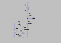
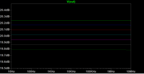
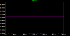
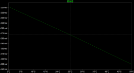
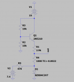
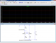
Simple singe-ended JFET amplifier, and gain as a function of temperature (15 to 45C in 5 degree steps) By replacing R1 with a positive tempco resistor (1400ppm) pretty good temperature stability is attained, but positive tempco resistors are a bit difficult to get (I have a couple dozen left over from a log amp project decades ago, but only one value.)
I am opening up for suggestions which would involve NTC resistors. I have some ideas...
Attachments
I am opening up for suggestions which would involve NTC resistors. I have some ideas...
A NTC (of much smaller value) in series with the source?
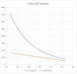
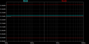
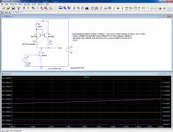
Here's an idea -- I haven't bread-boarded yet but have a bunch of Vishay type 3977 NTC thermistors on the way. By putting a resistor of equal value in parallel with the thermistor a fairly linear gradient is obtained. A 2.2k thermistor in parallel with a 2.2k resistor:
Attachments
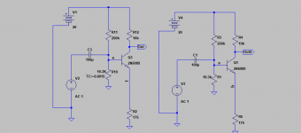
It's very common in IC design to use "replica biasing". If you assume that transistors A and B are near-identical (because they're built right next to each other on the same silicon substrate), you can attach all sorts of weirdass control systems and servomechanisms to transistor A, in order to establish its bias condition exactly where you want. Then use a copy of that bias voltage or bias current to operate transistor B at the same condition. But there are no servos or feeder-backers or sensors or other measurement apparatus wooly-boogers connected to B.
To apply here:
Find two JFETs whose gain vs temperature track each other closely. You know, match the transistors.
Build doodads and gizmos which affect the bias voltage and/or bias current of "A" and monitor its gain. Arrange via negative feedback to servo the bias on "A" until it runs at exactly the gain number "G" that you want.
Then copy the bias voltages / bias currents (mirrors!) to transistor "B" which is the single ended JFET amplifier. Voila. B has constant gain as temperature changes or as the batteries run down / mains voltage fluctuates.
Digging through the Vishay Application notes -- this could go a bit further down the food chain. The first employs a 330K NTC resistor with B of 3930 in parallel with 10.6K for a gradient of -0.0015, the second a 10.3K fixed value.
Attachments
Not sure what you really want. If it is "sub-dB accuracy" then my thoughts turn to Harold Black's negative feedback.... this is *exactly* what he was working on, amplifiers which do NOT depend on device parameters but only on simple passive networks which may be made stable.
If "noise" is an issue you probably need to define the impedance. Your later BJT design will have significant NF until source is above a few kOhm.
Another approach to temperature effects is to put the part in a thermostat oven. Or since JFETs tend to work better cold, an ice-box. Tupperware in a foam chest and an ice-tray dumped over a sealed preamp will stay within a degree of zero for hours.
Designing With Field-Effect Transistors Siliconix (Oxner or Evans) has a few words about the basics of temperature in JFETs.
Not sure what you really want.
but if you try sometime, you get what you need
Looking at precise and accurate measurement of noise, per the articles which have been written by Sam and Gerhard here and in Linear Audio.
Mark's comment wrt "boogery" reminds me of the pic my son took of his daughter, a living vector for the flu virus.
Mirthfully!
Designing With Field-Effect Transistors Siliconix (Oxner or Evans) has a few words about the basics of temperature in JFETs.
Thanks for the recommendation. The book is available for download!
- Status
- This old topic is closed. If you want to reopen this topic, contact a moderator using the "Report Post" button.
- Home
- Design & Build
- Construction Tips
- Temp Compensating SE JFET amplifiers