So I was reading a little bit on those sweep tubes the last days.
For a Class B or A/B stage they really have some nice properties.
They can handle high peak currents and it looks like they don't need a high bias to avoid cross overdistortion.
The output impedance is not to high so the OPT is easier to make.
Doing some searching I came to the 6LW6 / 26LW6 or 36LW6 looking very nice.
I also found that lundahl makes a nice transformer The LL2768 having an primary impedance of 680ohm.
https://www.lundahltransformers.com/wp-content/uploads/datasheets/2768.pdf
Using 4 pairs of 6LW6 this could really make some nice power.
I'm just wondering how far it's possible to go with these valves?
I was thinking on an amp based on this A Low Distortion Williamson Circuit.
Adding some cathode followers to directly drive the output tubes.
I'm still on the search for a nice and not to ordinary bass/sub amp with tubes. so looking at different ideas.
I've noticed that tubelab has some experience in these sweep tubes.
In simulation I was able to get over 800w out of those but I think that would really be killing tubes. (800mA peak per tube)
What would you guys recomment for screen voltage? this should be well stabilized and not to high. (150-200v?)
And what kind of plate voltage?
As I see it those sweep tubes should not be used in SE class A.
There intended operating conditions are more like class A/B with a cold bias and heavy peak currents.
Just like to hear some experiences. I searched the forum and read some things but need to know more if possible.
hmm that looks promising.
that means 100w from a pair in triode
SO in pentode means that means some serieus output.
As I have read so far the screens shouldn't get to high voltage but the anode can have.
I wanted to have a low THD drive and enough gain so I can add a little bit of feedback to lower the output impedance and have some control over the speaker.
One thing I've noticed in the simulation is that these tubes can easily oscillate
Maybe, maybe not. For that kind of output in triode, you're looking at peaking amperes into 250R or so... B+ around 300V.
If you keep the voltage down to around 300V in triode, you won't get oscillations... If you run the tube HOT all the time, it WILL run away on you... It's just a matter of time...
If you keep the voltage down to around 300V in triode, you won't get oscillations... If you run the tube HOT all the time, it WILL run away on you... It's just a matter of time...
That's why I think it's not a good idea to run it triode.
Keeping the screen grid low can help a lot I think.
The other thing is to keep the idle current also low.
I wonder if they suffer a lot from cross over distortion but reading some posts they don't seem to need a lot of idle current.
Keeping the screen grid low can help a lot I think.
The other thing is to keep the idle current also low.
I wonder if they suffer a lot from cross over distortion but reading some posts they don't seem to need a lot of idle current.
I'm just wondering how far it's possible to go with these valves?
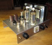
Here some reference. A pair of soviet sweep tubes 6P45S, ?Ub = 480 V, Ug2 = 155 V (must be stabilized), Ra-a = 2000 ohms, Pout is some 200 W at clipping (THD ~2%).
Power trafo is TA34M100 and opt TU34M100, both from Italian Inmadout.
Adding some cathode followers to directly drive the output tubes.
No need to use cathode followers. The "drive" of output tubes is done with voltage only, no current required.
Attachments
Last edited:
That's a nice reference indeed.
I was thinking something a like with 150v on the screens. around 500v Ub and then 4 pairs loaded with 680ohm Ra-a
The reason I was thinking about the cathode followers for driving the output is because there are 4 grids in parallel to drive and capacitance can become a problem....
If the driver itself is strong enough it shouldn't be a problem indeed.
Would the 6P45S be a better choice maybe?
No need to use cathode followers. The "drive" of output tubes is done with voltage only, no current required.
The plate curves I’ve seen on even the biggest sweeps seem to top out at around 400 to 600 mA at Vg1=0 if you keep Vg2 within ratings. You probably even want to back off from the max Vg2, just to make sure you don’t run away. That means you need AB2 drive if you want upwards of an amp of plate current, right? Even just a little into AB2 draws a couple milliamperes, and with these you probably want a lot.
Experiments I’ve done with ordinary tubes like KT88s show advantages at high power if followers are used. I would expect to use them with any sweep tube in push pull AB - if you wanted Tubelab-like power out of them.
The reason I was thinking about the cathode followers for driving the output is because there are 4 grids in parallel...
With multiple parallel tubes the cathode follower is a good idea. The problem is not the capacitance, if output tubes are pentode connected, but the low Rg required.
Would the 6P45S be a better choice maybe?
I don't know I have no practical experience with 6LW6 / 26LW6 or 36LW6. But for sure 6P45S and 6P42S are cheaper.
The plate curves I’ve seen on even the biggest sweeps seem to top out at around 400 to 600 mA at Vg1=0 if you keep Vg2 within ratings.
- 6P45S has Ia = 1.8 A @ Ug2 = 175 V, Ug1 = 0 V
- PL519 has Ia = 1.4 A @ Ug2 = 160 V, Ug1 = 0 V
That means you need AB2 drive if you want upwards of an amp of plate current...
In my case: (pentode mode) the positive peaks of drive AC stay always negative several volts.
Experiments I’ve done with ordinary tubes like KT88s show advantages at high power if followers are used.
Yes, I get 75 WPC from KT88's in triode on 450 volts into a 3300 ohm OPT. AB2 is required to get this power level.
I would expect to use them with any sweep tube in push pull AB - if you wanted Tubelab-like power out of them.
I use mosfet followers to eliminate bias shift and possible blocking distortion on transient peaks with sweep tubes, but the grid shouldn't go anywhere near zero with a bit fat sweep tube.
The plate curves I’ve seen on even the biggest sweeps seem to top out at around 400 to 600 mA at Vg1=0 if you keep Vg2 within ratings.
Here is my attempt at blowing a 6LW6 into orbit by tracing it's curves far beyond the data sheet recommendations. The screen grid was fixed at 150 volts .....yes I really did hit over 600 watts of dissipation for about 1/2 a second. The orange line at the top is +5 volts on G1. The blue line below that is 0 volts and each line represents a step of 5 volts. So, with 0 volts on G1 the plate is at 840 mA already with 50 volts on it.
160 watts from a pair was easy into a 3300 ohm load, but pushing things farther resulted in a fireball eating most of the ground plating off the PC board on my driver.....not the result of the tube, the circuit, or anything other than Dumm Blonde Engineering......Resistors have a voltage rating, and ignoring it by a factor of 3 or 4 can result in blown parts. Blown parts can make a big fireball when they are fed by a 1 KW power supply that has 1000uF of output capacitance.
I have seen 250+ watts from one pair of 35LR6 into a 2500 ohm load on 650 volts in Petes Big Red Board which does not use followers at all and does not do AB2. The tubes show a dull red glow in a dark room at this power level....36LW6's are BIGGER.
Attachments
Damn those things get some current flowing.
So if I look at this driving 680Ra-a should be even possible using 3 pairs...
Altough I'm gonna stick with 4 pairs, Would be better for lower output impedance (= speaker damping).
And it's a little less stress on the tubes
I really start to like those sweep tubes.
You don't need insane high voltages and the OPT can have a low impedance.
Thanks for the graphs
I have some Plitron 1250 ohm OPT's that are rated for "400 watts at 20 Hz." I plan to run 3 pair of 36LW6 on 650 volts, aiming for about 500 WPC. Two pair would make the required power, but three would last longer.
Your OPT is about half the impedance, so four pair would be about right.
Altough I'm gonna stick with 4 pairs
Your OPT is about half the impedance, so four pair would be about right.
Regardless of whose name is on the tube there are only two US manufacturers that made the 36LW6, Sylvania and GE. There is at least one Japanese manufacturer, but those tubes are rare.
There are at least 4 different variations of GE 6LW6's, two different flavors of Sylvania 6LW6's, and two different bulb diameters, 1.5 inches and 1.75 inches. Just make sure that the tubes you get are all the same.
GE seemed to experiment with several different kinds of heat radiating fins in their large bottle 6LW6s, including none at all. Most GE tubes are 1.75 inches in diameter. Most Sylvanias are 1.5 inches in diameter. The big GE 6LW6's with the big fins can eat 90 watts of continuous plate dissipation with no hint of red. The smallest Sylvanias with no heat fins will eat 45 to 55 watts before the red glow appears.
The multiple different flavor combinations is also common among the 26LW6's, but most of the 36LW6's that I have seem to be consistent. I have seen some oddities though, including two absolute monster 36LW6's that were made in Japan.
The Sylvania 36LW6 is usually 1.5 inches in diameter with the type number etched on the side and the letters USA under the number with no periods. The GE's are usually 1.75 inches, but I have seen skinny ones. They have the type number with the letters U.S.A. under it (with the periods) and the GE date code dots under that. This holds true no matter whose name is on the tube, and yes, you will find Sylvania made GE branded tubes, and GE branded Sylvania made tubes.
Both are good tubes. The earlier Sylvanias seem more consistent from tube to tube, but Sylvania turned out some pure trash in the later years of manufacturing. Ge's seem to have a wider spread from tube to tube, but I haven't found any GE's with blatant manufacturing mistakes in them.
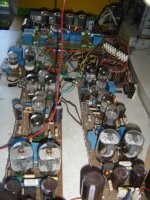
I got a box full of 42 Sylvania 35LR6's for too cheap......I found out why. None of the tubes had the tabs on the top of the plates twisted to keep the mica from falling off. Some were fine, and 4 of the properly made tubes made 525 watts at the edge of dull red glow. One of the others made fireworks because the beam former (G3) was loose and touched the plate. The worst is pictured here. The heater had fallen out of the cathode at the bottom, and the rest of the guts were loosely rattling about in the glass.
I have never seen any of the 'LW6's this bad though.
There are at least 4 different variations of GE 6LW6's, two different flavors of Sylvania 6LW6's, and two different bulb diameters, 1.5 inches and 1.75 inches. Just make sure that the tubes you get are all the same.
GE seemed to experiment with several different kinds of heat radiating fins in their large bottle 6LW6s, including none at all. Most GE tubes are 1.75 inches in diameter. Most Sylvanias are 1.5 inches in diameter. The big GE 6LW6's with the big fins can eat 90 watts of continuous plate dissipation with no hint of red. The smallest Sylvanias with no heat fins will eat 45 to 55 watts before the red glow appears.
The multiple different flavor combinations is also common among the 26LW6's, but most of the 36LW6's that I have seem to be consistent. I have seen some oddities though, including two absolute monster 36LW6's that were made in Japan.
The Sylvania 36LW6 is usually 1.5 inches in diameter with the type number etched on the side and the letters USA under the number with no periods. The GE's are usually 1.75 inches, but I have seen skinny ones. They have the type number with the letters U.S.A. under it (with the periods) and the GE date code dots under that. This holds true no matter whose name is on the tube, and yes, you will find Sylvania made GE branded tubes, and GE branded Sylvania made tubes.
Both are good tubes. The earlier Sylvanias seem more consistent from tube to tube, but Sylvania turned out some pure trash in the later years of manufacturing. Ge's seem to have a wider spread from tube to tube, but I haven't found any GE's with blatant manufacturing mistakes in them.
I got a box full of 42 Sylvania 35LR6's for too cheap......I found out why. None of the tubes had the tabs on the top of the plates twisted to keep the mica from falling off. Some were fine, and 4 of the properly made tubes made 525 watts at the edge of dull red glow. One of the others made fireworks because the beam former (G3) was loose and touched the plate. The worst is pictured here. The heater had fallen out of the cathode at the bottom, and the rest of the guts were loosely rattling about in the glass.
I have never seen any of the 'LW6's this bad though.
Attachments
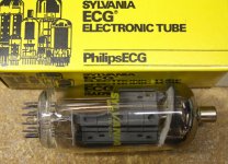
Let the Philips-bashing begin... every PhilipsECG tube and semiconductor I’ve ever used has failed in some either spectacular or unusual way. They’re just not worth a s....
A quad of 7868s I paid too much for all ran away and red-plated, then the screens melted and they were done. This was with cathode bias, in an amp designed for them. Went back to the original set with two of them with cracks in the glass (reason for replacement) and they continued to operate until I lost the power transformer. Even 12A*7’s died too soon with shorts to cathode that did interesting things in a series string. In TV service (anywhere) they never seemed to hold up very long. Neither did the horizontal output *transistors*. I wouldn’t trust Philips on an amp that could kill you.
A quad of 7868s I paid too much for all ran away and red-plated, then the screens melted and they were done. This was with cathode bias, in an amp designed for them. Went back to the original set with two of them with cracks in the glass (reason for replacement) and they continued to operate until I lost the power transformer. Even 12A*7’s died too soon with shorts to cathode that did interesting things in a series string. In TV service (anywhere) they never seemed to hold up very long. Neither did the horizontal output *transistors*. I wouldn’t trust Philips on an amp that could kill you.
Just a tought but would it be an idea of making a CF based output stage.
-Low distortion
-Low output impedance.
Main problem in pentode is the output impedance. So in CF this wouldn't be a problem. OPT is the same.
Only problem is the driving tube...... maybe using a split supply so the driver has a high voltage = high driving voltage capability.
I only don't really know a good tube for this duty. 6EM7 comes to mind.
Another problem is getting the screen voltage to follow the kathode voltage swings, otherwise it wouldn't be a pentode.
I think this can be done using an extra floating stabilised supply
that looks nice.
So far one thing that I've noticed with these sweep tubes is that they just keep delivering more current and not really reach saturation until far above the dissipation limit.
So a lot of peak current is available. for driving loudspeakers I think it's a good thing.
And in heavy class A/B that means a lot of power is possible.
In simulation the cathode follower output stage can deliver 200w+ without a problem. B+ is around 550v. THD is 0.56%.
That is just using an ideal driving stage and no feedback. so just the output stage.
The tubes where dissipating around 46w.
Personally I wouldn't try to get 200w from only 1 pair and this is just simulation.
Now how to get a driver that does 1100v Peak-Peak with low distortion.....
Add a little bit of feedback and this can really work
The needed drive is 550v Peak (1100v p-p)
Another nice thing is that the Output transformer is in the cathode so it sits around ground and not the HV line.
This could be something for using Big HV tubes as isolation is less critical.
So far one thing that I've noticed with these sweep tubes is that they just keep delivering more current and not really reach saturation until far above the dissipation limit.
So a lot of peak current is available. for driving loudspeakers I think it's a good thing.
And in heavy class A/B that means a lot of power is possible.
In simulation the cathode follower output stage can deliver 200w+ without a problem. B+ is around 550v. THD is 0.56%.
That is just using an ideal driving stage and no feedback. so just the output stage.
The tubes where dissipating around 46w.
Personally I wouldn't try to get 200w from only 1 pair and this is just simulation.
Now how to get a driver that does 1100v Peak-Peak with low distortion.....
Add a little bit of feedback and this can really work
The needed drive is 550v Peak (1100v p-p
)Another nice thing is that the Output transformer is in the cathode so it sits around ground and not the HV line.
This could be something for using Big HV tubes as isolation is less critical.
- Status
- This old topic is closed. If you want to reopen this topic, contact a moderator using the "Report Post" button.
- Home
- Amplifiers
- Tubes / Valves
- Sweep tubes in heavy class AB/B Simulations/Experiments