SSTART Pcb and power supply project - CNC Routing
Hi all,
I've recently finished building a small CNC router, and intend to use it to mill pcbs. There is of course quite a few steps in between knowing it can be done and achieving the goal, so this thread is intended to explore the process of learning to use the thing and producing some pcbs that I can actually use. As such I thought I'd pick something relatively simple to build and work through all the steps along the way. I should emphasize that I'm a learner at all of these things so this will serve as a documentation of my mistakes along the way I suspect...")
The planned project - the SSTART Preamp and a as yet to be determined power supply - I'm thinking something based on the psu described in the BOSOZ though at the moment
The SSTART Preamplifier Why on earth would anyone do such a thing? Article By Grey Rollins
http://www.firstwatt.com/pdf/art_bosoz.pdf
I intend to design a stereo pcb in eagle, then use
Welcome to PCBGCODE to generate the Gcode
the cnc router is a Shapeoko with a few little mods
Shapeoko | Precision by DefaultShapeoko | Precision by Default
using mach3 to drive the CNC router
ArtSoft USA - Home of Mach3 and LazyCam
And possibly using Mastercam to refine the Gcode
Mastercam CAD/CAM software
I'll do my best to detail what I accomplish along the way and we'll see how it goes.
Music to work to today - Cake - Comfort Eagle
Hi all,
I've recently finished building a small CNC router, and intend to use it to mill pcbs. There is of course quite a few steps in between knowing it can be done and achieving the goal, so this thread is intended to explore the process of learning to use the thing and producing some pcbs that I can actually use. As such I thought I'd pick something relatively simple to build and work through all the steps along the way. I should emphasize that I'm a learner at all of these things so this will serve as a documentation of my mistakes along the way I suspect...
The planned project - the SSTART Preamp and a as yet to be determined power supply - I'm thinking something based on the psu described in the BOSOZ though at the moment
The SSTART Preamplifier Why on earth would anyone do such a thing? Article By Grey Rollins
http://www.firstwatt.com/pdf/art_bosoz.pdf
I intend to design a stereo pcb in eagle, then use
Welcome to PCBGCODE to generate the Gcode
the cnc router is a Shapeoko with a few little mods
Shapeoko | Precision by DefaultShapeoko | Precision by Default
using mach3 to drive the CNC router
ArtSoft USA - Home of Mach3 and LazyCam
And possibly using Mastercam to refine the Gcode
Mastercam CAD/CAM software
I'll do my best to detail what I accomplish along the way and we'll see how it goes.
Music to work to today - Cake - Comfort Eagle
Last edited:
CNC Router
The router in question
https://picasaweb.google.com/lh/photo/IyToedK6uHs0tuBqzAWHDNMTjNZETYmyPJy0liipFm0?feat=directlink
The router in question
https://picasaweb.google.com/lh/photo/IyToedK6uHs0tuBqzAWHDNMTjNZETYmyPJy0liipFm0?feat=directlink
first pass at pcb
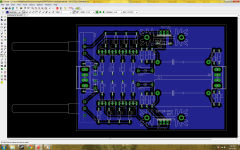
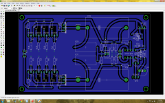
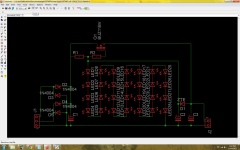
First spin at PCB.
I am no layout expert so please, constructive comments welcome.
Parts are not as labeled - nor are values as yet. I used roughly equivalent parts from the eagle library and I'll alter labels/values accordingly once it's nailed down.
I also will need to alter the design rules to better accommodate what the router will need to do to cut the pcb out. There are a variety of pads connected with cross shapes to traces - the mill cannot do those cuts (nor are they necessary).
I also have two placeholder parts until I find a spade connector part in the eagle library... these are for the 60V supply connections (labeled X1 and X2 for now)
Next Power Supply layout...
Attachments
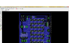
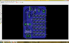
first pass at power supply pcb
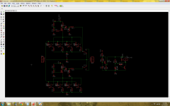
Copied from the design of the BOSOZ article by Nelson Pass (thank you sir!).
I'm using a pile of 5mm leds at the 63V reference due to the fact that I'm looking at about of 1000 of them right now... And the same caveats apply as the previous pcb, in that I've used what I think is an appropriate substitute part and will label values as needed later on should the basic layout be sound.
Music whilst doing this - CCR
Attachments
Stock to be used
I'll be using single sided copper clad pcb materiel. The PCB-Gcode outputs code for a two sided pcb if required but I thought I'd start gently. The point of this is quick and easy creation of pcbs without using FeCl and similar. Basically by the end of this I hope to just be able to throw some pcb materiel in the cnc machine and get a finished job out the other side.
I'll be using single sided copper clad pcb materiel. The PCB-Gcode outputs code for a two sided pcb if required but I thought I'd start gently. The point of this is quick and easy creation of pcbs without using FeCl and similar. Basically by the end of this I hope to just be able to throw some pcb materiel in the cnc machine and get a finished job out the other side.
Tweaking settings
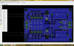
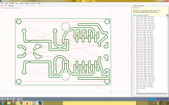
Setting up pcb-gcode to output something useful for my machine has been a little tricky.
For one, I intend to use a 1mm flat end bit to do the milling, and all the faq's I've read are oriented towards using an engraving bit (pointy). I have some .25mm bit's, but it doesn't seem worth it for a pcb thats all through hole parts, and where all the traces and pads can be made to be 1mm away from each other.
That was the next trick - setting up the design rules in Eagle to keep everything at least 1mm apart. Finding where to set pad sizes took a while, but I seem to have a setup that works now. As well as isolating the ground plane by 1.5mm, that seems to be the trick. Below is the output from pcb-gcode and from a cnc simulator (So I have an idea of what the hell the gcode actually represents)
Attachments
Well, cool. Let us know if the milling works, I've never heard of this. I detest FeCl, and have too much pride to pour it down the drain when it is used up. Hazwaste disposal is >$400 a 55 gal drum, not a service a diyer can use. I had heard you could etch PWB's with a mixture of HCl and strong peroxide, about the time Al Kaida started using peroxide to try to **** up airplanes. So peroxide disappeared from all the store haircare shelves, and HCl is out of fashion now as a pool cleaner, also. Best I can find without a hazmat UPS shipment is 6% HCl in Lysol for cleaning toilets (mixed with detergent).
Incidently, the phrase "PCB" is a bit out of fashion here, where they spent $xxxxxxxxx digging up the part of Bloomington where Westinghouse used to make capacitors with the chemical of the same name. Hammond started calling them "PWB"s for printed wire board.
Incidently, the phrase "PCB" is a bit out of fashion here, where they spent $xxxxxxxxx digging up the part of Bloomington where Westinghouse used to make capacitors with the chemical of the same name. Hammond started calling them "PWB"s for printed wire board.
Last edited:
Peroxide banned? I remember doing etching at high school with that mix... I would have been 16? Hilarious to think that would make me a terrorist suspect these days
I also had a few issues sourcing chemicals at some point. I had a quick look around to see if I could get some HNO3 and H2SO4 for doing some home anodizing, and the best luck I had was a lab chemical supplier. Admittedly, I'd have to drive about 2.5 hours to pick up but it's not completely unavailable.
I believe that HCl is also used in making Meth so I'm not sure you just have Al Qaeda to blame there...
I just realised that having googled a few things whilst writing this post that I'd now appear to be a drug manufacturing terrorist to whatever govt agencies track these things
I'll be sparking up the Router today to try my first run at milling a pcb - I'm not expecting much as I've made it a one pass cut but we'll have to see.
It works basically
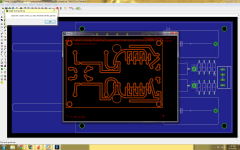
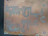
Basic principle is fine - the gcode output is all good (although I need to change a few things in the settings) and the cnc router seems to have worked well for the first half of the job.
The second half didn't go so well (I cut the job short in the end) I saw the mill miss a step or two and obviously after that everything was squew-if. I'd have to say though that the software side of all of this seems to be fine though; the issue would exist on the router hardware/electronics side.
Anyway, the top half is fine up to the mounting hole (top right) and then in the bottom half there's lots of errors.
I'll try again, using a .25mm bit and less demanding cuts. I was doing a .5mm depth single pass over the board, so I can see that that is unnecessarily deep.
Attachments
Last edited:
So!
Unsuprising news of the day - you can't mill with a .25mm bit. It's just too small.
I also discovered that you don't use a ground plane as such or the code will mill both sides of the trace - that of the trace and that of the polygon that is your ground plane. I'm sure that there must be a way to work around this...
Looks as if the technique of routing copper off a clad stock board is working well. Sorry about the stepper motor driver problem. I might look into this, 2 axis lead screw vises come up for <$80 sometimes used. It might have possibly less problems than a used digital stepper control assembly like you may have bought.
My system
The physical system itself works fine (I've the dual x drive version of the Shapeoko) but I bought some rather odd stepper motors which seem to have a higher resistance and inductance than most nema 17 units. They're getting significantly hotter than I've seen before, and the jobs seem to fail after running for a while - making me suspect that heat is the issue.
That said - the control box is built out of ebay parts, so who knows? I have a G540 control unit and a full set of larger motors so I will give that a spin instead sometime soon.
If you're thinking of making something yourself from what you describe, you'll probably want some beefy motors to overcome the stiction in a cheaper set of leadscrews. A mate and I built a cnc router with a 850mm by 850mm workspace a while back and used proper leadscrews and antibacklash nuts - worth every penny as trying to accommodate the rig not moving when you reverse direction due to <ahem> sloppy nuts is hard to do in software. I'm happy to be contacted if you'd like to discuss - I was hugely inspired by a couple of local cnc builders and the time they took to help saved days.
Thanks, I'm the kind of digital idiot they write books for (about). Since intel assembly language and MSAccess basic, everything I've tried has just sat there with a blank screen. I was actually thinking of cranking the vise by hand using the 100% visual feedback control system; so lead screw slop would be less of a problem.
I've been building circuits on Nema LE laminate by drilling a lot of holes and using leaded components and hooking the wires together before soldering (actual insulated wire between components), but they don't always stay soldered. I kicked the board on my latest project in December and broke something, and am struggling this week with wires breaking off a tiny transformer that I can't make hooks out of the leads (too short) on my latest project. A PWB gives better support to your solder connections, even if you have to grind out every line and pad by hand. Thanks for detailing your advanced technology project. Even if I just make pads for particular PWB compatible components out of scraps of copper clad board, this technique could improve reliability.
Oddly, I picked up a lot of tiny stepper motors & drives in scrap obsolete Ishida scale units for food bagging. The aren't big enough to drive a 2 axis vise, but I might try something someday. Maybe a needle valve control for an analog fuel injection system. US fuel is now totally incompatible with carburators, but I refuse to drive a car that won't go 5 miles after the fan belt breaks ( as computer electrical control motor vehicles do). Have fun.
Last edited:
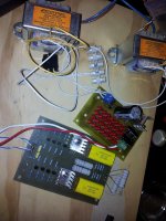
Well I knocked up a prototype
...and it seemed to work fine.
I still need to do a bit more work on the cnc machine in order to get consistent output. I've received some engraving bits which should make the cutting easier, and I'm yet to install the new driver box. So progress here is a few weeks off.
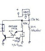
So in the mean time I built a board and power supply to test the design. I matched all the j310's to about 25mA and just bunged a couple of ifr610's in without matching. The power supply was built and worked perfectly using a random fet out of my parts bin - think its a buz71A. First pass was pretty good on the scope, but I decided to change a few things.
First - I ditched the low pass filter on the front end. I'll reconsider should it prove necessary
Secondly - I added a circuit to put a delay on the connection of the outputs after a delay. I'm yet to sim/test this so I'm not confident it's a goer as yet. Advice happily accepted on this...
Where I'm at is detailed visually below.
I'll etch a new version and see how that works...
...and it seemed to work fine.
I still need to do a bit more work on the cnc machine in order to get consistent output. I've received some engraving bits which should make the cutting easier, and I'm yet to install the new driver box. So progress here is a few weeks off.
So in the mean time I built a board and power supply to test the design. I matched all the j310's to about 25mA and just bunged a couple of ifr610's in without matching. The power supply was built and worked perfectly using a random fet out of my parts bin - think its a buz71A. First pass was pretty good on the scope, but I decided to change a few things.
First - I ditched the low pass filter on the front end. I'll reconsider should it prove necessary
Secondly - I added a circuit to put a delay on the connection of the outputs after a delay. I'm yet to sim/test this so I'm not confident it's a goer as yet. Advice happily accepted on this...
Where I'm at is detailed visually below.
I'll etch a new version and see how that works...
Attachments
Last edited:
I came across this site yesterday, he has been working on a CNC pcb router as well.
joebrown.org.uk
Also, have you considered using NXP BF862 as a sub for J310, much lower noise, but only available in SOT-23 pkg.
Your jfet ckt is similar to the Pearl2 MM phono pre-amp from Passdiy, may want to refer to it is as well.
Rick
joebrown.org.uk
Also, have you considered using NXP BF862 as a sub for J310, much lower noise, but only available in SOT-23 pkg.
Your jfet ckt is similar to the Pearl2 MM phono pre-amp from Passdiy, may want to refer to it is as well.
Rick
Last edited:
Cheers for the input rsavas - on his site joebrown references two software packages worth looking at it seems.
Of Itself So - Line Grinder, Gerber to GCode Isolation Milling
Of Itself So - Line Grinder, Gerber to GCode Isolation Milling
I'll give them a look later on.
As for the jfet sub stitution, I'm pretty committed to the j310's now given I bought 100 of em, and then took the time to match them... that was a boring couple of hours! Anywho, it's an option should I revisit the design.
Reading the pass article now - thanks for the steer.
Of Itself So - Line Grinder, Gerber to GCode Isolation Milling
Of Itself So - Line Grinder, Gerber to GCode Isolation Milling
I'll give them a look later on.
As for the jfet sub stitution, I'm pretty committed to the j310's now given I bought 100 of em, and then took the time to match them...
that was a boring couple of hours! Anywho, it's an option should I revisit the design.Reading the pass article now - thanks for the steer.
Last edited:
- Status
- This old topic is closed. If you want to reopen this topic, contact a moderator using the "Report Post" button.
- Home
- Source & Line
- Analog Line Level
- SSTART Pcb and power supply project