I have a couple of these speaker protection modules, which run off 12 - 15V AC
I want to use them in my diy plate amp which runs on a 24v DC SMPS.
The description said they require a seperate power supply, But I was hoping to use the same 24v SMPS and an isolator like a dc-dc converter.
This requires me to mod them so they take DC instead of AC.
I think I did this correct but I just want to check with some more knowledgeable person if I did it right.
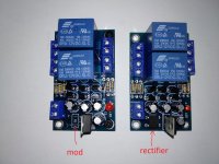
I removed the rectifier and bridged the contacts.
What would the recommended input DC voltage be in this situation? still 12 - 15v?
I want to use them in my diy plate amp which runs on a 24v DC SMPS.
The description said they require a seperate power supply, But I was hoping to use the same 24v SMPS and an isolator like a dc-dc converter.
This requires me to mod them so they take DC instead of AC.
I think I did this correct but I just want to check with some more knowledgeable person if I did it right.
I removed the rectifier and bridged the contacts.
What would the recommended input DC voltage be in this situation? still 12 - 15v?
Attachments
This requires me to mod them so they take DC instead of AC.
I think I did this correct but I just want to check with some more knowledgeable person if I did it right.
I removed the rectifier and bridged the contacts.
What would the recommended input DC voltage be in this situation? still 12 - 15v?
Actually to use it on DC you didn't need to change anything. Just hook it up and go... the diodes in the rectifier would steer the current for you and, as a neat side effect, it wouldn't matter which way you connected the DC.
If it wants 12vac, that's an RMS value so you could probably feed it up to ...
12 * 1.41 == ~17vdc without any problems.
Check the voltage rating on the caps, before you do.
Last edited:
If you want to use these protection circuits for Class D amplifier like TPA3116, which is supplied with only one rail voltage 24V - they won't work!!!
They are only for single ended amplifiers with symmetric power supply, like +/-24V!
Check the voltage regulators on these PCBs - I think they are LM7812 or similar - they need at least 14-15V to work properly. You can supply the PCBs with 24V from SMPS, but you may put small heatsinks on the voltage regulators.
If you want to use these protection circuits for Class D amplifier like TPA3116, which is supplied with only one rail voltage 24V - they won't work!!!
They are only for single ended amplifiers with symmetric power supply, like +/-24V!
Check the voltage regulators on these PCBs - I think they are LM7812 or similar - they need at least 14-15V to work properly. You can supply the PCBs with 24V from SMPS, but you may put small heatsinks on the voltage regulators.
The regulator is indeed LM7812.
Why can't these boards be used with TPA3116? Why would the power supply requirements of the amp affect this module?
This particular project is for a small subwoofer, and I will only use one channel of the protection board.
I was planning to use a dc -dc converter to bring the 24v down to 15v. But if I can get away with 24v and a heatsink, I might give that a try.
Last edited:
Because these protection boards are designed to work around 0V, as is the output of SE amplifiers with dual rail PSU.
All bridge amplifiers with single rail PSU have 1/2 of the PSU at their outputs! Not 0V!
The difference between the two output pins for one channel is near 0V, but if you measure every output against the GND, you'll see 12V, when the PSU is 24V.
If you want to use protection boards - find boards, that are designed for bridge amplifiers, with single rail power supply!
Last edited:
Thanks for the information.
I also have one of these modules, currently in use with IRS2092. Would these work with TPA3116 as well?
DC 12 24V UPC1237 Dual Channel Speaker Protection Circuit Board Boot Mute Delay Integrated Circuits-in Integrated Circuits from Electronic Components & Supplies on AliExpress
I also have one of these modules, currently in use with IRS2092. Would these work with TPA3116 as well?
DC 12 24V UPC1237 Dual Channel Speaker Protection Circuit Board Boot Mute Delay Integrated Circuits-in Integrated Circuits from Electronic Components & Supplies on AliExpress
Because these protection boards are designed to work around 0V, as is the output of SE amplifiers with dual rail PSU.
All bridge amplifiers with single rail PSU have 1/2 of the PSU at their outputs! Not 0V!
The difference between the two output pins for one channel is near 0V, but if you measure every output against the GND, you'll see 12V, when the PSU is 24V.
If you want to use protection boards - find boards, that are designed for bridge amplifiers, with single rail power supply!
Do the relay contacts switch to ground?
A proper design would have the speaker contacts floating to avoid the exact problem you're describing.
Thanks for the information.
I also have one of these modules, currently in use with IRS2092. Would these work with TPA3116 as well?
You probably don't need the extra circuitry at all. The TPA3116 chip includes it's own internal current, heat and voltage protections, as well as mute and standby to allow for thumpless turn on/off. Unless the board you're using is completely brain dead no external speaker protection is needed.
The relay contacts just connect and disconnect the signal output and the load.
The GND is common.
So, if they are just making and breaking the speaker connection, why does it matter whether the amp is btl or not... or for that matter... whether it's class A B AB or D?
Now if one side of the relay contacts was grounding the speaker, okay you got a point ... but if the contacts are simply opening and closing the wire to the speaker, I don't see the issue.
Most of these have a common gnd for both channels that won't work with btl
The actual relay contacts are grounded? That's dumb.
No... There's a common ground which they use for the DC detection. So you could use one for each channel but can't use them in stereo on a BTL amp.The actual relay contacts are grounded? That's dumb.
Anyway as had been discussed, TPA3116 has plenty of protection built in... There's really no need IMHO
You probably don't need the extra circuitry at all. The TPA3116 chip includes it's own internal current, heat and voltage protections, as well as mute and standby to allow for thumpless turn on/off. Unless the board you're using is completely brain dead no external speaker protection is needed.
the board I've been using is this one in BTL mono mode.
TPA3116D2 50Wx2 Official Version Finished Stereo Digital Power Amplifier Board | eBay
It features no contacts on the pcb for standby or mute.
The problems I've been having with my Tang Band w5-1138 subwoofer is a nasty on/off thump. But even worse; when I switch the power button on, after the thump the driver escurses quite a bit for about a second. I'm afraid this will ruin the driver real quick.
I hoped to solve the problem completely with a boot delay module since I have them laying around anyway. But I realize this tpa board might also be the culprit. Suggestions for good mono tpa3116 boards are very welcome. I really like the one Sure/Wondom made, but for this application that one is too large.
For this protection boards, there is no matter the class of the amplifier - A, AB, B, C, D, H...
It is important the amplifier to be with single ended output AND dual rail PSU, so the output is near 0V, when there is no signal at the input of the amplifier.
You can modify the output of the bridge amplifier with single rail PSU, as adding 1000uF capacitors in series with the load and use one board for one channel, but you loose the protection function, because there is no DC component after the caps and the protection boards will work only as delay switch for the speakers. I haven't try this, just thinking...
No... There's a common ground which they use for the DC detection. So you could use one for each channel but can't use them in stereo on a BTL amp.
Anyway as had been discussed, TPA3116 has plenty of protection built in... There's really no need IMHO
How would you suggest utelizing the mute function?
Would a single switch to switch the mains power to the power supply, as well as disconnect the mute-gnd connection work somehow? For example with a switch that has a 'normally open' and 'normally closed' side? Seems tricky to have ac and dc on the same switch.
Or would it be better to have the SMPS always on and just control the amp on/off by the mute function of the amp board?
Most of the newer TPA3116 designs are using the mute and stdby pins of the amplier as an on/off switch leaving the SMPS always on and the bulk capacitors always charged. Basically the front panel switch is a "shut up" button.

The data sheet outlines the correct usage.
http://www.ti.com/lit/ds/symlink/tpa3118d2.pdf
Since this is a pre-fab board and the chip won't operate unless both Mute (Pin 12) and Stanby (Pin 2) are at a logic 1 (+5v) it is very likely the pins are internally configured on the board. A bit of circuit tracing will probably reveal an RC circuit already in place... you can generally extend this time to avoid the thump by tack soldering a larger value capacitor across the original part.
- Status
- This old topic is closed. If you want to reopen this topic, contact a moderator using the "Report Post" button.
- Home
- Amplifiers
- Class D
- Speaker protection boot delay module modification.