Hello fan's of snubbers ")
When using snubber design on a chipamp, 100-220uF + 0,1uF, is it enough capacitance to use on the pcb itself, or should I ad more capacitance before them on the pcb.
Im designing a board right now and thinking about using 100-220uF + 0,1uF on the pcb before each LM3886, and then use larger cap's in the power section that will be on another pcb. Will it be enough capacitance or should I ad, say 2200-4700uF on the LM-pcb to before the snubbers?
Best regards...
100-220 uF is not really enough. You can use up to about 2200 uF without the need for snubbers.
The idea of snubbers is to allow larger amounts of capacitance to be used without the 'harmful' affect that can have on the sound quality. So yes, you can have 2200, 4700, or even 10,000 uF providing they are snubbered.
The idea of snubbers is to allow larger amounts of capacitance to be used without the 'harmful' affect that can have on the sound quality. So yes, you can have 2200, 4700, or even 10,000 uF providing they are snubbered.
Nuuk said:100-220 uF is not really enough. You can use up to about 2200 uF without the need for snubbers.
The idea of snubbers is to allow larger amounts of capacitance to be used without the 'harmful' affect that can have on the sound quality. So yes, you can have 2200, 4700, or even 10,000 uF providing they are snubbered.
Hi Nuuk and thank you. Im aware of that I need more capacitance than those 100-200uF, but I want to know if i have to put the bigger cap's on the pcb, or if its enough to have them off-board, in the psu-part of the amp.
Attachments
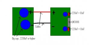
Put the 100nF on the chipamp power pins.
Put the 220uF next to the chipamp power pins.
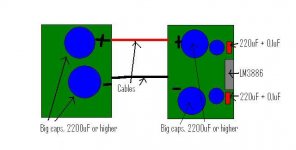
Put the 2200uF as close to the chipamp as possible, aim for less than 30mm of track length.
My 2200uF caps have just arrived. 16mm diam by 25mm tall. I intend putting these on the P2P in lieu of the 220uF.
Put the 220uF next to the chipamp power pins.
Put the 2200uF as close to the chipamp as possible, aim for less than 30mm of track length.
My 2200uF caps have just arrived. 16mm diam by 25mm tall. I intend putting these on the P2P in lieu of the 220uF.
My 2200uF caps have just arrived. 16mm diam by 25mm tall. I intend putting these on the P2P in lieu of the 220uF.
Panasonic ECA by any chance Andrew?
no, Forever from Rapidonline.Nuuk said:Panasonic ECA by any chance
Never heard of them! but they are cheap £0.33each for 12.
I'm trying Carlos FM's recommendation.
Well thank you both of you. I will try to put it as close as possible. Hand-solder the 0,1uF directly on the supply pins must be the best solution i think.
Since the positive supply pins on the LM are internaly connected, pin 1 and 5, do you really need to have a trace to both of them, or can I skip pin nr 5 for a easyer layout?
Since the positive supply pins on the LM are internaly connected, pin 1 and 5, do you really need to have a trace to both of them, or can I skip pin nr 5 for a easyer layout?
I have never put a cap on pin 5 and it seems to work fine without. (I uses a short wire link between pins 1 and 5).
The Ronaldo of Gaincloning!
I'm trying Carlos FM's recommendation.
The Ronaldo of Gaincloning!
what does that mean?Nuuk said:The Ronaldo of Gaincloning!
Gain Clone is a specific implementation. I think Carlos FM's implementation is NOT Gain Clone nor anything even close to resembling it.
Was CarlosFM permanently sin-binned?AndrewT said:no, Forever from Rapidonline.
Never heard of them! but they are cheap £0.33each for 12.
I'm trying Carlos FM's recommendation.
Nuuk said:
The Ronaldo of Gaincloning!
Wasn't he eventually slain by a Saracen?
Gain Clone is a specific implementation
True but is seems to be used for most chip-amps these days.
I was referring to both of them being Portuguese!
an 100nF X7R soldered to the pins of an LM3886, LM3875, LM4780 is about as useful as t eats on a bull if you don't get the ground side connection close and wide. Elsewise it's just a radiator.
Rolando, Orlando -- now getting seriously OT, but I would highly recommend to anyone reading "The Song of Roland" in the medieval French, I have a copy with a side by side translation into contemporary French bought at FNAC.
and getting even further afield -- Seamus Heaney's translation of Beowulf.
Rolando, Orlando -- now getting seriously OT, but I would highly recommend to anyone reading "The Song of Roland" in the medieval French, I have a copy with a side by side translation into contemporary French bought at FNAC.
and getting even further afield -- Seamus Heaney's translation of Beowulf.
Be sure to connect pins 1 & 5 on the PCB. The LM3886 has 2 pins because there are more bond wires for higher current capability. There are the same number of bond wires on the -Vee as well but they are configured differently so there is only one pin. Thinking they are connected internally and only connecting one will lead to trouble. The trace is small enough you only need 1 cap close to the pins. I have never used more than one and see no problems.
-SL
-SL
My thoughts
I like big caps off board, medium caps on board, and small low z on power pins. And a small film rail to rail close to the chip.
Right now that is 10K - 12K close to the rectifiers, bypassed with 0.033 ufd film and 0.1ohm resistors in series. The low value resistor damps ringing, making this a snubber. 220 - 330 ufd low ESR on the board close to the chip. 0.1 ufd film rail to rail. And finally a 22 ufd to each power pin. The 1 and 5 pins are connected via the PCB.
Works GREAT! I think using a real low impedance electro on the power pins is the ticket. Currently have 22 ufd 50 v Panasonic FM in this location. The rails are +/- 36.5 volts, so it limits the caps to 50 volt rated. If I had lower rails, say 30 volt, I would solder in the new Rubycon ZG ultra low impedance caps. They are small (low inductance) and the lowest listed ESR I have seen. Cheap too. But Newark only has them to 35 volts.
The distance between the big electros, medium size, and small value puts resistance and inductance in series to tame any ringing. The big caps will supply the current to the LM3886 when needed.
OT Wish CarlosFM was still around. He was always thinking of ways to improve his circuits. And sharing the info.
George
Hi, I`m about finishing mi GC with Brians`s boards, and wanna ask which .1 caps are best for snubber? in power supply I use 3300uF Vishay low ESR caps (have 12 but will test how many/much sounds best), caddock and Alan Bradley resitors, in amp board I use caddocks and rikens, and black gate std caps
now, is it worth to buy some "expensive" .1 caps, and is it possible to get some sound improvement, or Vishay Bc is just fine (http://uk.farnell.com/1166036/passi...BC-COMPONENTS-2222-470-76104&_requestid=14410)
i have already ordered lot of these, now I`m making order from partsconnexion and have some extra $$ (wow can`t believe saying "extra" ), so I would like to order some better .1 caps
need suggestion, no partsconnexion.com limitations, just ~10$/cap limit
now, is it worth to buy some "expensive" .1 caps, and is it possible to get some sound improvement, or Vishay Bc is just fine (http://uk.farnell.com/1166036/passi...BC-COMPONENTS-2222-470-76104&_requestid=14410)
i have already ordered lot of these, now I`m making order from partsconnexion and have some extra $$ (wow can`t believe saying "extra"
), so I would like to order some better .1 capsneed suggestion, no partsconnexion.com limitations, just ~10$/cap limit
AndrewT said:I'm trying Carlos FM's recommendation.
Hi Andrew,
What are your findings regarding that specific decoupling/bypass arrangement (2200||220||0.1 uF)?
Thanks,
Baka
I think this is a rather normal approach.Baka said:
Hi Andrew,
What are your findings regarding that specific decoupling/bypass arrangement (2200||220||0.1 uF)?
Banned in fact, maybe not for life though.jackinnj said:
Was CarlosFM permanently sin-binned?
- Status
- This old topic is closed. If you want to reopen this topic, contact a moderator using the "Report Post" button.
- Home
- Amplifiers
- Chip Amps
- Snubber question