I have a pair of Snell Type 1's. I love them, but the tweeter's fuse holder on the left speaker broke, so I thought I'd take this opportunity to rebuild the crossovers and install them in an external box.
My idea of rebuilding crossovers is to replace the caps and rewire, leaving the chokes alone.
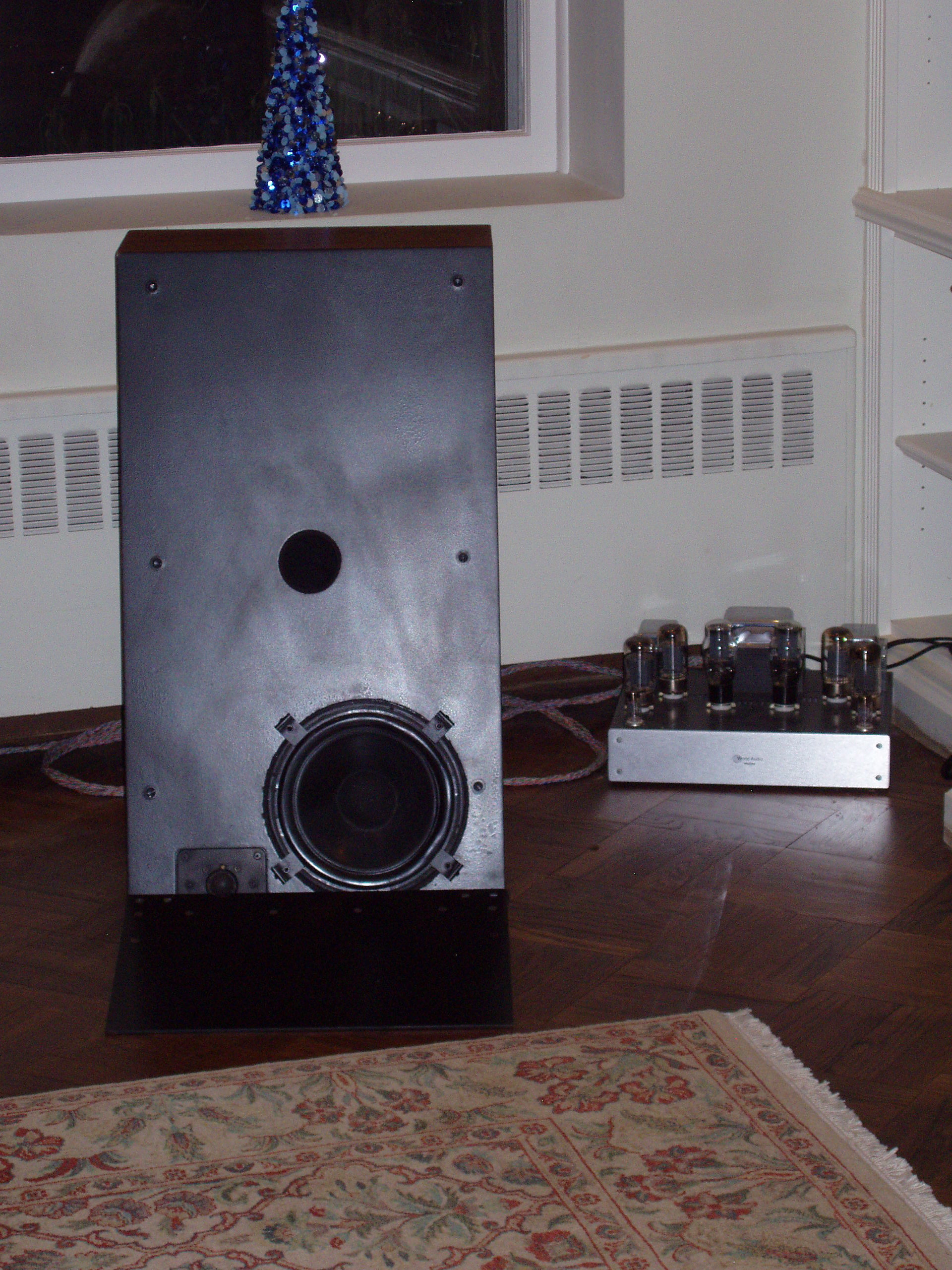
Here's what Type 1's look like...
And a bit of a close up...
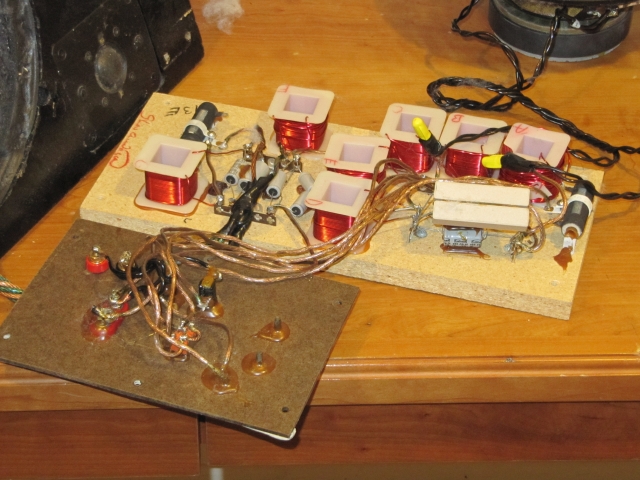
Here's the crossover...
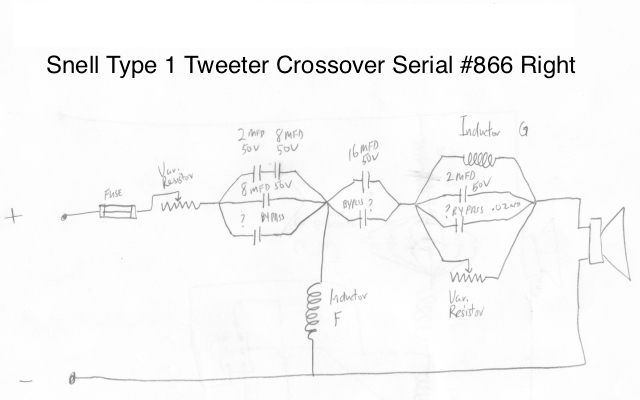
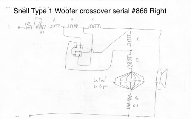
Here's the crossover schematics drawn out. You can see on the woofers, there is a 3 way switch that adjusts the midrange level. I haven't mapped this out yet. But the switch in the center is "normal" with the up position being "Increase 1" and down position being "Increase 2."
As you can see, there are MANY capacitors. I count 22 for the pair of loudspeakers. With 12 big ones in the woofer x-over.
Also, I plan on replacing the wiring with multiple strands of individually teflon insulated silver plated copper wiring.
Before I start this project, I would love to hear any opinions from the team!
Thanks in advance,
Dan
My idea of rebuilding crossovers is to replace the caps and rewire, leaving the chokes alone.
Here's what Type 1's look like...
An externally hosted image should be here but it was not working when we last tested it.
And a bit of a close up...
Here's the crossover...
Here's the crossover schematics drawn out. You can see on the woofers, there is a 3 way switch that adjusts the midrange level. I haven't mapped this out yet. But the switch in the center is "normal" with the up position being "Increase 1" and down position being "Increase 2."
As you can see, there are MANY capacitors. I count 22 for the pair of loudspeakers. With 12 big ones in the woofer x-over.
Also, I plan on replacing the wiring with multiple strands of individually teflon insulated silver plated copper wiring.
Before I start this project, I would love to hear any opinions from the team!
Thanks in advance,
Dan
Last edited:
Part of the reason for the multiple caps is that Snell allways engaged in production tuning of each crossover. For whatever curve the particular drivers gave they would adjust key components to get the curve within +-0.5 dB of the reference. Typically they would start with low cap values and add small increments to get to the right value. Also inductors were a little high and turns were pulled off as needed.
Make sure you keep the right crossover with the right cabinet and drivers.
David S.
Make sure you keep the right crossover with the right cabinet and drivers.
David S.
Those are cool speakers Dan! Do you know what year they were made? I'd imagine those caps are ready to be replaced, but I really don't know. The driver surrounds look like they are still in good shape, but it's hard to see from the photo on my monitor. Looks like they were using the floor as a mirror similar to the CBT without the array.
I'd measure each individual group of caps all together to see the precise value. With all the variance/tolerances of the caps, they may be significantly off from simple addition of stated values. Of course maybe those old lytics won't measure right so addition may actually be better. If the measured value is no where near the sum, I'd go with the sum. If none of the experts here chime in I'd ask at a classic speaker forum before performing any surgery.
Dan
Those are cool speakers Dan! Do you know what year they were made? I'd imagine those caps are ready to be replaced, but I really don't know. The driver surrounds look like they are still in good shape, but it's hard to see from the photo on my monitor. Looks like they were using the floor as a mirror similar to the CBT without the array.
I'd measure each individual group of caps all together to see the precise value. With all the variance/tolerances of the caps, they may be significantly off from simple addition of stated values. Of course maybe those old lytics won't measure right so addition may actually be better. If the measured value is no where near the sum, I'd go with the sum. If none of the experts here chime in I'd ask at a classic speaker forum before performing any surgery.
Dan
Agree, you should go with the sum rather than a measurement. Too many NPE's there and any one could be bad based on their age and reputation.
A key decision you need to make is whether to recap with new film caps or stick with NPE's (mew ones of course) and a pF ceramic disk BP just like they used.
Last edited:
Those are cool speakers Dan! Do you know what year they were made?
Not sure what year exactly, but I think '80 or '81. there is almost no documentation on these speakers. the Snell website didn't even list them in their speaker archive!
The driver surrounds look like they are still in good shape, but it's hard to see from the photo on my monitor. Looks like they were using the floor as a mirror similar to the CBT without the array.
The surrounds and cones are in great shape. Word is that Peter Snell bought the drivers and then coated them with god knows what. I can see on the back side of the cone that it looks to be clear poly-something , with an applied black coating on the front side. The surrounds look to be some kind of rubber with the same black coating applied to the cones. The tweeters are in great shape.
Yes, the idea was the tweeter mounting and ramp eliminated floor reflection.
Good advice on the caps. I think adding up the uF is the way to go. I expect to buy plastic film caps. I priced out Hovland Music Caps for the pair at over $500!
I might go this route for the tweeters, but maybe cheaper plastic caps for the woofer.
Thanks,
Dan
Here's a review on the speakers....(sorry, these are big)
http://members.rennlist.org/lt_texan/Snell1p1.pdf
http://members.rennlist.org/lt_texan/Snell1p2.pdf
http://members.rennlist.org/lt_texan/Snell1p1.pdf
http://members.rennlist.org/lt_texan/Snell1p2.pdf
Hovland has gone out of business. I hope you got a great price.
Best value for the $ are Sonicaps IMHO.
ouch, must have been a old website. thanks for the recommendation!
ouch, must have been a old website. thanks for the recommendation!
If you find the sound a bit bright after the film recap, you should reconsider NPE's or, adding a low value (0.25-0.5 ohms) resistor in series with the film caps to compensate for the normally higher ESR of NPE's than film types. This will restore the overall system integration that matches the original.
If you find the sound a bit bright after the film recap, you should reconsider NPE's or, adding a low value (0.25-0.5 ohms) resistor in series with the film caps to compensate for the normally higher ESR of NPE's than film types. This will restore the overall system integration that matches the original.
There's a variable resitor in the circuit for the already
")
Last edited:
There's a variable resitor in the circuit for the already
I believe that one was there to balance the eff. of the tweeter with the woofer. Adjusting that might help, but keep in mind it's located ahead of the cap bundles.
Just to give you a little history of these: I was President/Chief Engineer of Snell for 5 years some time back. These are Peter Snell designs that predate me. The concept was that a speaker above the floor allways has its response degraded by the floor bounce. If you lower the speaker the reflection gets closer in time to the direct sound and the degradation (comb filtering) moves up in frequency. Now, if you could lower the drivers to the point where they were actually touching the floor (and even have the tweeter partially submerged) then the floor bounce effect would be totally negated.
So that is the purpose of the apron on the front of the speaker. It allows you to sink the tweeter partially into the surface and get a very smooth response. The downside is the image height is a little low! As I understand we didn't sell that many of them because the market felt they were "too unusual".
At the factory they were known affectionately as "the wheelchair ramp" speaker.
David S.
Well David, I guess that's one way to establish credentials!!!!!!!!!!!! 
I cannot pretend to understand exactly what is going on with the tweeter crossover. My Snell K's and EIII's are both much simpler 2nd order cap and choke.
I see the variable resistor in parallel with the choke and cap just before the tweeter. I take it that is where some of the fine tuning took place to dial in the final caps and chokes.
Also, I don't understand why Peter Snell put two groups of caps with the choke to ground in between. And then the choke/cap/resistor series.
Oh well, these a lot of caps! Will be very expensive to replace them all with boutique caps. More than the speakers cost me. Oh my, decisions decisions.
Funny, in the tweeter, the first and second group of caps calculate out to an equivalent 6uF (if I got the math right), but I don't dare move the position of that choke between the two. Something tells me that is that way on purpose.
And Speaker Doctor, thanks for the Snell.no site. I had found that a couple years ago when I bought these speakers used. It is a bit dead, but I posted this there too (as I did at the Classic Speakers website).
I've always had very good luck with advice and info here with my other posts usually in analog sources and tube amp forums. (Thanks to all!!!)
Anyone want to write up their analysis of the crossovers????
Last edited:
Here's the woofer with the midrange settings on
- normal
- increase 1
- increase 2
- normal
- increase 1
- increase 2
An externally hosted image should be here but it was not working when we last tested it.
Anyone want to write up their analysis of the crossovers????
In the tweeter circuit, the first var. resistor simply adjusts the overall SPL output. The next two cap bundles and parallel coil comprise a typical 3rd order HP filter. The last paralleld bundle is a parallel trap/notch filter designed to attenuate a hump in the HF response. The var. resistor there is what fine tunes the hump flat and that's pretty much it. My experience with a model A xover years ago left me with the impression that Peter S. stocked a limited variety of cap values and mixed and matched as needed to attain a target uF value and then bypassed the lot with a pF ceramic cap.
In the woofer circuit the 3 series wired coils are in and out of the circuit depending on the switch position. In any case, any more than one in play they become additive in mH value. All still first order though. The different values attainable via switching simply adjust the position of the knee of the LP transfer function. That large assemblage just ahead of the woofer is a notch filter which is tuned to address a resonant peak in its response.
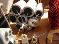
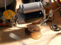
I've attached two close up pics of Model A cap bundles. One is of a large midrange bundle with a BP cap barely visible at the bottom. The other is of a smaller bundle lifted off the pF ceramic BP cap.
Attachments
I cannot pretend to understand exactly what is going on with the tweeter crossover. My Snell K's and EIII's are both much simpler 2nd order cap and choke.
Anyone want to write up their analysis of the crossovers????
The tweeter crossover looks like a 3rd order highpass. The elements just prior to the tweeter are a notch circuit. That resistor will effect depth of notch (higher resistance = deeper). There must have been a troublesome bump that needed taming and that varied from speaker to speaker.
Resistor at the front of the circuit is simply a variable level control to set broadband tweeter level.
I wouldn't touch these pots unless you had an RTA, in which case it would be interesting to see the effects and fine tune the pair!
Good luck,
David S.
Thanks a lot guys!
Why does it make more sense AFTER it is explained?
I'm leaning toward Solen caps in the woofer crossover and SpeakerDoc's recommendation of Sonicaps in the tweeter circuit.
I'll follow the 1% rule on bypass caps (and see what the pF caps are spec'd at).
Since I will mount the crossovers in a box remote from the speakers, I will be able to adjust the level resistors if necessary. I don't want to touch the resistors in the notch filter. Nor do I want to mess with the choke coils. (I don't have any equipment to measure results.)
Of course, I'll not destroy any of the original pieces so it can all be put back together (in case the Smithsonian calls).
Documentation to come once I get the caps.
Thanks,
Dan
- Status
- This old topic is closed. If you want to reopen this topic, contact a moderator using the "Report Post" button.
- Home
- Loudspeakers
- Multi-Way
- Snell Type 1 Crossover Rebuild