Recently my Marconi TF 2331 distortion factor meter "pasted away". A real loss because it served me for years to measure the THD of my build tube amplifiers.
I now have the idea to build a simple THD measuring instrument myself using a twin-t notch filter at 1 kHz. Browsing on this forum about this subject, I did not find anything which satisfied my needs. Most of them are way too complicated to fabricate myself . Browsing the internet gave me a design by Kenneth Kuhn from 2009. Its publication "A simple Notch Type Harmonic Distorsion Analyzer" was just what I needed. So I started to analyze the Kuhn circuit diagram with the help of LTspice. Apart from the input and output coupling capacitors which value I increased to give the notch more narrow bandwidth necessary for nill attenuation of the second harmonic, its attenuation at 1 kHz is not larger (deeper) than 40dB while the author stated it would reach 60dB.
Can someone give me other simple designs please?
The Kuhn circuit diagram I analyzed with LTspice in the attachment.
Attachments
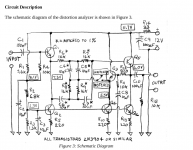
You need to match the components to a lot better than 1% to get anything like a -60dB null (that's one part in a thousand). Start with 1% or better rated parts and select the best matching sets. And you are also limited by the loss-tangent of the capacitors so use good film caps, PP or PTFE, for best results.
The simple transistor buffers in that circuit may contribute to the distortion being measured at higher amplitudes, good opamps are the way to go if so.
If you want an accurate 1kHz frequency you'll need to build the resistances out of series or parallelled sets to get the right value (15915 ohms if the capacitors are spot-on 10nF) Adding small valued series trimmers (or large valued parallel trimmers) might be useful for adjustments.
Have you considered a computer audio interface and some of the software available? Most internal soundcards will be capable of quite precise distortion measurement of a tube equipment. For high voltage make a simple voltage divider, for galvanic isolation use a notebook running on batteries.
Have you considered a computer audio interface and some of the software available? Most internal soundcards will be capable of quite precise distortion measurement of a tube equipment. For high voltage make a simple voltage divider, for galvanic isolation use a notebook running on batteries.
Yes, I have.
In the recent past I used a software oscilloscope and using it to probe my tube amplifiers I noticed disturbing signales at its output which I could not get rid of.
First I thought it was due to parasitic oscillating but putting my finger on some parts of the wiring did not change its frequency.
You would expect that this would change the frequency a little bit because the condition for oscillation changed, but it was not.
Using a hardware scope and switching off my computer, that disturbance signal disappeared. So I am now using a hardware scope.
That's why the sound card for THD measurements is not an option for me. I do not have a notebook to test if this problem does not exist then but I doubt it.
JoeAlders, can you elaborate on what 'disturbance signal' was seen on the hardware scope? Were you using a separate input signal source to the amp, or an input signal generated from software and exported via soundcard?
I'd strongly suggest that something in your setup was not right, rather than just the use of a software oscilloscope function being the sole cause of your initial problem.
Another problem that can show up is when the DUT amplifier does not have a 'direct' connection between input signal gnd and output signal gnd. Sometimes an amp can have a poor gnd system, and signal and hum currents can end up flowing via the test rig (where the test rig has its own common ground connection between line out and line in circuitry).
JoeAlders, can you elaborate on what 'disturbance signal' was seen on the hardware scope? Were you using a separate input signal source to the amp, or an input signal generated from software and exported via soundcard?
I'd strongly suggest that something in your setup was not right, rather than just the use of a software oscilloscope function being the sole cause of your initial problem.
Another problem that can show up is when the DUT amplifier does not have a 'direct' connection between input signal gnd and output signal gnd. Sometimes an amp can have a poor gnd system, and signal and hum currents can end up flowing via the test rig (where the test rig has its own common ground connection between line out and line in circuitry).
Reading your comment " .....on what 'disturbance signal' was seen on the hardware scope? ",
I wrote instead:"...Using a hardware scope and switching off my computer, that disturbance signal disappeared."
But to show you what I meant I again used the software scope and measured the output signal of the tube amplifier and to my frustration I could not reproduce it anymore

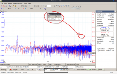
Now that output signal was as clean as measured with the hardware scope although I used the software AWG which is available also in that software scope. Luckily I had one picture of the FFT plot stored which is shown below. There a 55kHz disturbance is seen and this could also be noticed on the 1kHz sinewave as it was superimposed on it.
Anyway, I do not know what kind of experience others have but for me as "old-school" electronics designer, I find it way easier to use the hardware scope that its software brother......but that is another story.
In the mean time I will repeat the experience a few times and see if the output signal stays clean and let you know the results.
Attachments
Here is a simple but very capable DIY THD analyzer:
Antique Radio Forums • View topic - measuring distorsion
It is for fixed 700 Hz frequency, useful in the audio range.
Also do read up on state variable filters to better understand the operation of the tester.
Peter
Antique Radio Forums • View topic - measuring distorsion
It is for fixed 700 Hz frequency, useful in the audio range.
Also do read up on state variable filters to better understand the operation of the tester.
Peter
- Status
- This old topic is closed. If you want to reopen this topic, contact a moderator using the "Report Post" button.
- Home
- Design & Build
- Equipment & Tools
- Simple type harmonics distorsion analyser advise