What actually happens with the signal gain structure within the miniDSP x-over?
I start with the “Input Signal RMS meter.
Measurement set-up:
Signal Source Hameg Function Generator HM8030-3 (Rout:50 Ohm)
Sinusoidal Signal Frequency:1281 Hz.
Instrument for mVrms and db measurement : Keithley 175 True RMS Multimeter
Instrument for mVpp measurement and clipping monitoring: Hameg Oscilloscope HM203-7
DUT:
MiniUSB kit: 2xIn, 4xOut. It is the 2V Input version. (5 Vdc supplied through the USB port. Output loaded with 10kOhm).
Plug-in: MiniDSP 2 Way advanced (Release date 17/02/2011)
I applied the sinusoidal signal to Input 1. The path through the outputs is flat.
X-over and filters are bypassed. Zero attenuation on the gain sliders.
Input 1 and Output 1 are monitored for level and waveform clipping.
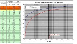
On the attachment you can see the results of the measurement.
Two thinks are of importance here:
A. The flat output starts clipping when the Input RMS meter of the plug-in SW reads anything above the “–6” reading. (the output RMS meter for flat settings reads the same as the input meter).
The sinusoidal signal amplitude corresponding to this clipping threshold is 2.228Vrms (or 6.118Vpp).
B. The law that governs the input RMS meter of the plug-in does not follow the db law of neither voltage nor power measurements.
More downstream measurements tomorrow (hopefully).
>Note: B above seems to be a “technicality” but bears some importance for non-flat measurements (later).
George
I start with the “Input Signal RMS meter.
Measurement set-up:
Signal Source Hameg Function Generator HM8030-3 (Rout:50 Ohm)
Sinusoidal Signal Frequency:1281 Hz.
Instrument for mVrms and db measurement : Keithley 175 True RMS Multimeter
Instrument for mVpp measurement and clipping monitoring: Hameg Oscilloscope HM203-7
DUT:
MiniUSB kit: 2xIn, 4xOut. It is the 2V Input version. (5 Vdc supplied through the USB port. Output loaded with 10kOhm).
Plug-in: MiniDSP 2 Way advanced (Release date 17/02/2011)
I applied the sinusoidal signal to Input 1. The path through the outputs is flat.
X-over and filters are bypassed. Zero attenuation on the gain sliders.
Input 1 and Output 1 are monitored for level and waveform clipping.
On the attachment you can see the results of the measurement.
Two thinks are of importance here:
A. The flat output starts clipping when the Input RMS meter of the plug-in SW reads anything above the “–6” reading. (the output RMS meter for flat settings reads the same as the input meter).
The sinusoidal signal amplitude corresponding to this clipping threshold is 2.228Vrms (or 6.118Vpp).
B. The law that governs the input RMS meter of the plug-in does not follow the db law of neither voltage nor power measurements.
More downstream measurements tomorrow (hopefully).
>Note: B above seems to be a “technicality” but bears some importance for non-flat measurements (later).
George
Attachments
Some more hours spent today on measurements, checking the operation of the input attenuation slider.
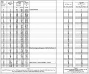
I connected the signal source at the input. Input signal was the 1281 Hz sinusoid held fixed at the clipping threshold of 2.228Vrms. Attenuation was accomplished by the Input slider from the plug-in software.
The db meter and the oscilloscope were connected at the flat Output 1 (which is loaded by 10kOhm).
Input RMS meter and Output RMS meter agree on their indications, when the path from input to output is flat.
Each step of the input (and output) attenuation slider corresponds to one db of attenuation. That’s good.
The not so good thing is that, for one db of attenuation through the slider , two are registered by the input (and output) “RMS” meter of the miniDSP !
Detailed measurements (Table 2) and some head-scratching , revealed the law that governs these “RMS” meters (see top of Table 3).
More to follow later.
George
Attachments
Last edited:
KenTripp and Charlie, thank you for posting
Charlie, IMHO it is more a matter of insufficient technical documentation rather than a technical discrepancy.
Some wrap-up here.
The Input attenuation slider is implemented in the digital domain, past the input, after the A/D conversion. So, when a signal applied at the input has an amplitude greater than the clipping threshold level, it overdrives (clips) the A/D converter.
Adjusting the input attenuator to a lower click, will not attenuate the analog input signal that would prohibit the A/D clipping. It will attenuate the digital clipped signal which will be further processed and furnished to the outputs in it’s clipped form.
If the signal applied to the input has a high amplitude but still below clipping level, it may clip during processing if excess boosting is applied through filters.
E.g. A signal 6db below the clipping level is applied to the input(remember, this signal will be read by the input meter as “-18”).
Then If a filter is added with a gain of anything more than 6db -or a succession of filters with total boosting greater than 6db- the digital signal will “clip”. This will manifest itself at the Output meter which will read above the “- 6”.
This clipping due to filter “overboosting” can be canceled by applying attenuation through the output slider. The amount of attenuation in db has to be equal to the excess gain applied by the filters.
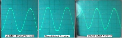
This trick has a limit. This limit is 24db. If the excess gain is more than 24 db, the output attenuators are not able to render signal undistorted. In this case the output signal will not look clipped but bent and skewed, looking like a slew limited signal.
http://www.diyaudio.com/forums/attachment.php?attachmentid=332122&stc=1&d=1361568128
Strange behavior indeed. But this made me look at the ADAU1701 data sheet http://www.analog.com/static/imported-files/data_sheets/ADAU1701.pdf which verified this 24db overhead.
Now things became clear to me. The internal flow is as follows.
1. Analogue signal entry.
2. A/D converter.
3. Input attenuator.
4. Pre-filter bank.
5. X-over filter bank.
6. Post-filter bank.
7. Output attenuator.
8. D/A converter.
9. Reconstruction filter.
10. Analogue signal exit.
Everything between A/D converter output and D/A converter Input (digital domain) gets an +24db max overhead, while the A/D and D/A operate on 0db max level. The RMS meters monitor each A/D digital output and each D/A digital input respectively (there are 2 A/D and 4 D/A converters). I repeat here that this “0db max level” is the “-6” reading of the RMS meters.
For the limited case of steady state input signal, all one has to do to ensure “overload free” operation, is to observe both input and output meters not to exceed the “- 6” reading. ( Warning. This does not cover the case of filter boost above the 24db).
The sad truth is that the x-over kit will never work with steady state signals when installed in an audio system. Music signal is dynamic.
The meters are not true peak meters, not even quasi peak meters. They are db FS (digital Fulll Scale) monitors, albeit with a peculiar calibration and an unspecified -but certainly long, close to VU meter -response time .
http://www.diyaudio.com/forums/attachment.php?attachmentid=332123&stc=1&d=1361568128
Thus , I am inclined to treat them as db FS monitors with VU meter ballistics, which means that for monitoring already processed speech and music signal, I should adjust for 14db -18db below the 0db level. This corresponds to max observed meter indications of “–34” to “ –42”.
Too low a level you will object. Not so.
Standard practice dictates a maximum of -20db level for VU meters (that would be a max “-46” reading with these meters).
In fact, the reason that I started this search was that, while listening to music (ok, on classic and opera recordings) I heard the sound to become harsh and bottomed when these meters were “peaking” occasionally at –24 –26. This has been shown now to be 9-10db below digital clipping.
“Harsh and bottomed” means a lot of distortion already.
George
Charlie, IMHO it is more a matter of insufficient technical documentation rather than a technical discrepancy.
Some wrap-up here.
The Input attenuation slider is implemented in the digital domain, past the input, after the A/D conversion. So, when a signal applied at the input has an amplitude greater than the clipping threshold level, it overdrives (clips) the A/D converter.
Adjusting the input attenuator to a lower click, will not attenuate the analog input signal that would prohibit the A/D clipping. It will attenuate the digital clipped signal which will be further processed and furnished to the outputs in it’s clipped form.
If the signal applied to the input has a high amplitude but still below clipping level, it may clip during processing if excess boosting is applied through filters.
E.g. A signal 6db below the clipping level is applied to the input(remember, this signal will be read by the input meter as “-18”).
Then If a filter is added with a gain of anything more than 6db -or a succession of filters with total boosting greater than 6db- the digital signal will “clip”. This will manifest itself at the Output meter which will read above the “- 6”.
This clipping due to filter “overboosting” can be canceled by applying attenuation through the output slider. The amount of attenuation in db has to be equal to the excess gain applied by the filters.
This trick has a limit. This limit is 24db. If the excess gain is more than 24 db, the output attenuators are not able to render signal undistorted. In this case the output signal will not look clipped but bent and skewed, looking like a slew limited signal.
http://www.diyaudio.com/forums/attachment.php?attachmentid=332122&stc=1&d=1361568128
Strange behavior indeed. But this made me look at the ADAU1701 data sheet http://www.analog.com/static/imported-files/data_sheets/ADAU1701.pdf which verified this 24db overhead.
Now things became clear to me. The internal flow is as follows.
1. Analogue signal entry.
2. A/D converter.
3. Input attenuator.
4. Pre-filter bank.
5. X-over filter bank.
6. Post-filter bank.
7. Output attenuator.
8. D/A converter.
9. Reconstruction filter.
10. Analogue signal exit.
Everything between A/D converter output and D/A converter Input (digital domain) gets an +24db max overhead, while the A/D and D/A operate on 0db max level. The RMS meters monitor each A/D digital output and each D/A digital input respectively (there are 2 A/D and 4 D/A converters). I repeat here that this “0db max level” is the “-6” reading of the RMS meters.
For the limited case of steady state input signal, all one has to do to ensure “overload free” operation, is to observe both input and output meters not to exceed the “- 6” reading. ( Warning. This does not cover the case of filter boost above the 24db).
The sad truth is that the x-over kit will never work with steady state signals when installed in an audio system. Music signal is dynamic.
The meters are not true peak meters, not even quasi peak meters. They are db FS (digital Fulll Scale) monitors, albeit with a peculiar calibration and an unspecified -but certainly long, close to VU meter -response time .
http://www.diyaudio.com/forums/attachment.php?attachmentid=332123&stc=1&d=1361568128
Thus , I am inclined to treat them as db FS monitors with VU meter ballistics, which means that for monitoring already processed speech and music signal, I should adjust for 14db -18db below the 0db level. This corresponds to max observed meter indications of “–34” to “ –42”.
Too low a level you will object. Not so.
Standard practice dictates a maximum of -20db level for VU meters (that would be a max “-46” reading with these meters).
In fact, the reason that I started this search was that, while listening to music (ok, on classic and opera recordings) I heard the sound to become harsh and bottomed when these meters were “peaking” occasionally at –24 –26. This has been shown now to be 9-10db below digital clipping.
“Harsh and bottomed” means a lot of distortion already.
George
Attachments
Last edited:
This is all over my head, but can I ask if adding a transformer before would be of benefit to an issue such as this? It raises the signal level to my PLLXO (passive line level crossover) and I want to move to Minidsp soon.
P.S. I would use the analogue outputs from my preamp to the minidsp, so signal level would be even more important in my set-up
P.S. I would use the analogue outputs from my preamp to the minidsp, so signal level would be even more important in my set-up
Last edited:
Some more hour
Thanks for posting this George.
")
The Input attenuation slider is implemented in the digital domain, past the input, after the A/D conversion. So, when a signal applied at the input has an amplitude greater than the clipping threshold level, it overdrives (clips) the A/D converter.
Ahhh....

Last edited:
Great work ! Makes a lot of sense, and perhaps explains the problems some have had trying to correctly apply gain staging strategies to these units.
The miniDSP folks need to address this issue with improved technical documentation and perhaps some explicit level matching advice. A reply to this topic from them would help a lot.
In light of this new knowledge I have reset my system levels and improved s/n by nearly 5dB which will be important for my new, WIP, much more sensitive, speaker system. Damn that dodgy meter calibration....
Rgds
blakkcloudsgather
SAC
Measure the output of your preamplifier first.
Dave and blakkshepe, thank you. I did this work for me and I thought to share it.
To summarize the important points without going into difficult technical details:
1. Each input meter monitors the output of the respective A/D output.
2. Each output meter monitors the input of the respective D/A output.
3. The clipping threshold corresponds to a reading of “- 6” on miniDSP meters.
4. The numerical reading of these meters does not correspond to db values.
5. These meters are not peak meters, their indications do not fluctuate that fast to follow the peak envelope of the music signal. The output of the source that drives these miniDSP kits should be adjusted so as the meters show much lower values than the clipping limit of “- 6”.
How low, depends on the recordings:
I would suggest for heavily compressed music, the input meter long term indication reach not higher than “- 26” (10db headroom).
For uncompressed contemporary music not higher than “-42” (18db headroom).
For demanding recordings (jazz, classic and opera fall in this category) not higher than “-54” (24db headroom).
For live unprocessed takes, “-66” reading (30db headroom) may be high. Watch for lower settings.
6. The total boost of frequency bands through filters, better not exceed 24db.
No 1 and 2 are not problems. They implement proper decisions from the SW designers. But they have to be explained in the technical documentation in order to inform users. Ditto for No 6.
No 3 and 4 are real problems. As an interim action, they should have been addressed ASAP with bold letters in the technical documentation. They’d better be corrected in the next revision of the plug-ins.
Last, No 5 is a technical decision but IMHO a questionable one for this application.
These meters should be treated as an aid in establishing proper gain settings by the user.
VU meter types need knowledge and experience (not assumed to be had by a typical user) for to be used properly.
A choice of Peak type meters would be more appropriate there.
A compromise could be reached by retaining the chosen meters and adding a peak “led” indicator for each meter. But I thing that this “compromise” will require more computational resources than designing for Peak meters (with some hold-up time) straight on.
I will e-mail the dev team of miniDSP to let them know. I hope they will respond.
George
PS. I measured the clipping threshold on a new 2x4 kit I bought recently. It uses jumpers for changing the input sensitivity.
For 2V setting, the threshold input level before clipping was 2.223Vrms for an output of 0.861Vrms.
For 0.95V setting, the threshold input level before clipping was 0.999Vrms for an output of 0.861Vrms.
These measurements (as well as the first 2x4 - fixed input level- kit measurements ) are in agreement with the max input for full scale in the ADAU1701 data sheet.
Last edited:
SAC
Measure the output of your preamplifier first.
Dave and blakkshepe, thank you. I did this work for me and I thought to share it.
To summarize the important points without going into difficult technical details.
1. Each input meter monitors the output of the respective A/D output.
2. Each output meter monitors the input of the respective D/A output.
3. The clipping threshold corresponds to a reading of “- 6” on miniDSP meters.
4. The numerical reading of these meters does not correspond to db values.
5. These meters are not peak meters, their indications do not fluctuate that fast to follow the peak envelope of the music signal. The output of the source that drives these miniDSP kits should be adjusted so as the meters show much lower values than the clipping limit of “- 6”. How low, depends on the recordings.
I would suggest for heavily compressed music, the input meter long term indication reach not higher than “- 26” (10db headroom).
For uncompressed contemporary music not higher than “-42” (18db headroom). For demanding recordings (jazz, classic and opera fall in this category) not higher than “-54” (24db headroom).
For live unprocessed takes, “-66” reading (30db headroom) may be high. Watch for lower settings.
6. The total boost of frequency bands through filters, better not exceed 24db.
No 1 and 2 are not problems. They implement proper decisions from the SW designers. But they have to be explained in the technical documentation in order to inform users. Ditto for No 6.
No 3 and 4 are real problems. As an interim action, they should have been addressed ASAP with bold letters in the technical documentation. Then, they’d better be SW corrected in the next revision of the plug-ins.
Last, No 5 is a technical decision but IMHO a questionable one for this application.
These meters should be treated as an aid in establishing proper gain settings by the user.
VU meter types need knowledge and experience (not assumed to be had by a typical user) for to be used properly for this task.
A choice of Peak type meters would be more appropriate there.
A compromise could be reached by retaining the chosen meters and adding a peak “led” indicator for each meter. But I thing that this “compromise” will require more computational resources than designing for Peak meters (with some hold-up time) straight on.
I will e-mail the dev team of miniDSP to let them know. I hope they will respond.
George
PS. I measured the clipping threshold on a new 2x4 kit I bought recently. It uses jumpers for changing the input sensitivity.
For 2V setting, the threshold input level before clipping was 2.223Vrms for an output of 0.861Vrms.
For 0.95V setting, the threshold input level before clipping was 0.999Vrms for an output of 0.861Vrms.
These measurements (as well as the first 2x4 - fixed input level- kit measurements ) are in agreement with the max input for full digital scale in the ADAU1701 data sheet.
Last edited:
The meters might be calibrated to random noise signals and not for sinusoids
Are you able to repeat the test with random noise? (Maybe I can do so this evening)
Also not sure where actual rms calculation takes place? In the DSP, PIC or PC? Being a bit slow might be a problem with data-transfer between miniDSP and plugin. I agree it would be nice to have a peak indicator!
Are you able to repeat the test with random noise? (Maybe I can do so this evening)
Also not sure where actual rms calculation takes place? In the DSP, PIC or PC? Being a bit slow might be a problem with data-transfer between miniDSP and plugin. I agree it would be nice to have a peak indicator!
Last edited:
Sorry for the unintentional double posting (posts # 9 and # 10) . It would be nice if a moderator could delete one of them.
You can try if you wish but you’ll get more confused. See for example here:
http://www.meyersound.com/pdf/cinema_technical_papers/cinema_calibration_tech_report.pdf
What is to keep from this?
A. There is 14db to 15.7db difference between the Peak and RMS values on all these test signals.
B. Their RMS value are to be held 21 db to 28db below the Digital Full Scale.
C. Their Peak value are to be held 6.8 db to 15.8db below the Digital Full Scale (the 6db overhead for even the True professional PPMs was a known factor from the analog past)
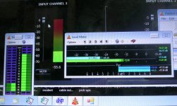
As you can see from the screenshot I have posted, ( http://www.diyaudio.com/forums/attachments/minidsp/332123d1361568172-signal-level-minidsp-x-over-meters-screenshot.jpg ) the relationship is not much different there (shown: Bit Depth Meter, Vu Meter, Peak Meter and the miniDSP RMS Meter, all registering their indications while monitoring in parallel one channel from the same FM radio station program)
Take PC out of this.
I would say no.
It would be useful
George
. It would be nice if a moderator could delete one of them.CurrymanThe meters might be calibrated to random noise signals and not for sinusoids
Are you able to repeat the test with random noise? (Maybe I can do so this evening)
You can try if you wish but you’ll get more confused. See for example here:
http://www.meyersound.com/pdf/cinema_technical_papers/cinema_calibration_tech_report.pdf
What is to keep from this?
A. There is 14db to 15.7db difference between the Peak and RMS values on all these test signals.
B. Their RMS value are to be held 21 db to 28db below the Digital Full Scale.
C. Their Peak value are to be held 6.8 db to 15.8db below the Digital Full Scale (the 6db overhead for even the True professional PPMs was a known factor from the analog past)
As you can see from the screenshot I have posted, ( http://www.diyaudio.com/forums/attachments/minidsp/332123d1361568172-signal-level-minidsp-x-over-meters-screenshot.jpg ) the relationship is not much different there (shown: Bit Depth Meter, Vu Meter, Peak Meter and the miniDSP RMS Meter, all registering their indications while monitoring in parallel one channel from the same FM radio station program)
Also not sure where actual rms calculation takes place? In the DSP, PIC or PC?
Take PC out of this.
Being a bit slow might be a problem with data-transfer between miniDSP and plugin.
I would say no.
I agree it would be nice to have a peak indicator.
It would be useful
George
I think the problem here George as Curryman has alluded to is that the data transfer between the board and the software isn't fast enough to keep up with the peaks. And the peak hold would have to be done in the software.
The meters themselves whilst being more or less useless for music signals are, apart from reading 2db for every 1db change to the attenuators reasonably accurate for steady state signals.
So I just run the input attenuators at 0db and have adjusted the analog input level to the board so the meters read -9.3db for a 1khz 0db down (ie. flat out) signal off a test CD. As CD is my loudest analog source (only by a couple of db) this works out fine.
I don't apply any eq boost at all (just cut if needed) so this works fine and the 3.3db gives just a bit of extra headroom for safety.
For a typical loud "pop" track the input meters read just into the high 20's.
Obviously if your were applying large amounts of boost via eq you would have to take this into account and reduce the signal to the board by a similiar amount.
George, I am very thankful for your work on this. I use MiniDSP for first prototyping speakers, before creating an analog analog. This is very useful information.
The question I would like to throw at you and others is the following: your measurements show how important it is to get the gain structure right. Too much input level and it starts to clip, and too little ... what then? The lower the signal, the lesser bits will be used in the AD-DA conversions. Since I run these prototypes from an analog signal with volume control, I must have listened to music coded with 8 bits or even less. The remarkeable thing is that this does not seem to degrade the sound quality perceptually that much. In other words, I would argue to stay on the safe side, and allow for more headroom than you instinctively would. Am I out on a limb here?
Anyways, the reason I translate the MiniDSP settings into an analog active filter is so that gain structure falls out of the equation, but I am almost tempted not to bother.
The question I would like to throw at you and others is the following: your measurements show how important it is to get the gain structure right. Too much input level and it starts to clip, and too little ... what then? The lower the signal, the lesser bits will be used in the AD-DA conversions. Since I run these prototypes from an analog signal with volume control, I must have listened to music coded with 8 bits or even less. The remarkeable thing is that this does not seem to degrade the sound quality perceptually that much. In other words, I would argue to stay on the safe side, and allow for more headroom than you instinctively would. Am I out on a limb here?
Vacuphile thank you for your kind words.
We have to be as much out on a limb here as much out have opted to be in the professional fields.
See Meyer Sound link
Consider how much more $$$ they have to invest for “throwing away” (reserve for) 21 db to 28db on the huge audio installations in theatres, auditoriums, planetariums ect. It would be instructive if Ed Simon and Tom Danley chime in here to give us first hand information on the topic (I bet they will admit that compressors have saved their pockets).
In broadcasting (big money there too) , 28db headroom is not enough.
For a typical loud "pop" track the input meters read just into the high 20's.
For a typical compressed material
, you are marginally OK.I think the problem here George as Curryman has alluded to is that the data transfer between the board and the software isn't fast enough to keep up with the peaks.
I have said that I doubt it. I have to think over for a way to test it. (*)
And the peak hold would have to be done in the software.
Apart from input level scaling, input anti-aliasing filtering and output low pass filtering, everything else is done in software.
George
(*) Now see this quote from ADAU1701 data sheet:
ADAU1701 programs can be loaded on power-up either from a serial EEPROM through its own self-boot mechanism or from an external microcontroller. On power-down, the current state of the parameters can be written back to the EEPROM from the ADAU1701 to be recalled the next time the program is run.
My interpretation is that the sw resides inside 1701 and executed from within. But I may be wrong.
>Edit (Serial port, SPI port and Multipurpose Pins tmax is in the tens of ns. It is only the I2C Port that has tmax in the hundreds of ns) .
Last edited:
Dear All,
First off, Thanks to George for bringing up this issue along with some good investigative work. Few weeks ago we did get a warning that we should have a look at it. We already started into looking into it to review what was the issue. It was a 2 fold issue it seems:
- A bug in the software (easy the fix)
- An incorrect type of DSP block used for the metering (harder to fix since it would mean "breaking the configuration")
Since Monday as we learned of the issue and found a fix by modifying the DSP structure. We are now going ahead and started to update all DSP structure for the metering to perform as it should. Problem is that it will unfortunately break the DSP configuration as previous .xml file will not be compatible anymore. (Shifted address)
In the future, we might see how we can build a script to "update" them. A second step though. In the next few days, we'll first post a new set of plug-ins with updated DSP block for monitoring and make an announcement. Hoping this info helps and thanks for your patience as we work through this issue.
Feel free to email us if you have any questions.
DevTeam
In the meantime, you can have a look and download these peak meter programs (configurable and calibreable)
Audio Level Meter
George
Audio Level Meter
George
- Status
- This old topic is closed. If you want to reopen this topic, contact a moderator using the "Report Post" button.