First off, Merry Christmas!!!
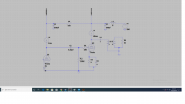
Hoping to get some opinions on a SET unregulated CLCLC design related to crosstalk. I am designing a SET amp with CCS plate loaded MH4 drivers and EL34 outputs as strapped triodes. The amplifier schematic is in a good place, I am just working out the kinks in the power supply. This is my first attempt to design my own amp rather than a kit!
My question is on crosstalk. I was originally going to only have a single power supply rail, i.e. not splitting left and right channels from the power supply, and the identical B+ would be sent to all four tubes. The drivers are CCS loaded, so isolated from the power supply, which would leave the two triode strapped EL34.
My C-L-C-L-C design right now goes:
U18/20 rectifier - 10uF - 6H 200mA 150Ohm - 65uF - 6H 200mA 150Ohm - 175uF - plates
My options right now are:
A) run both EL34 off the same power supply rail without splitting the channels and accepting any crosstalk
B) splitting the power supply at the 65uF cap, each channel having its own second 6H choke and 175uF cap
Can I expect a significant decrease in crosstalk with option B, and is it worth the extra cost in dollars and physical real estate?
I have been reading Morgan Jones' books diligently. He has a formula related to power supply AC output impedance and crosstalk. My understanding is the AC output impedance in a SET amp is roughly equivalent to the ESR of the final cap in the supply, which is 2mOhm. Given this impedance and the formula he uses, the crosstalk from a single rail is quite low, but again I am new to much of this so any help would be very much appreciated")
Hoping to get some opinions on a SET unregulated CLCLC design related to crosstalk. I am designing a SET amp with CCS plate loaded MH4 drivers and EL34 outputs as strapped triodes. The amplifier schematic is in a good place, I am just working out the kinks in the power supply. This is my first attempt to design my own amp rather than a kit!
My question is on crosstalk. I was originally going to only have a single power supply rail, i.e. not splitting left and right channels from the power supply, and the identical B+ would be sent to all four tubes. The drivers are CCS loaded, so isolated from the power supply, which would leave the two triode strapped EL34.
My C-L-C-L-C design right now goes:
U18/20 rectifier - 10uF - 6H 200mA 150Ohm - 65uF - 6H 200mA 150Ohm - 175uF - plates
My options right now are:
A) run both EL34 off the same power supply rail without splitting the channels and accepting any crosstalk
B) splitting the power supply at the 65uF cap, each channel having its own second 6H choke and 175uF cap
Can I expect a significant decrease in crosstalk with option B, and is it worth the extra cost in dollars and physical real estate?
I have been reading Morgan Jones' books diligently. He has a formula related to power supply AC output impedance and crosstalk. My understanding is the AC output impedance in a SET amp is roughly equivalent to the ESR of the final cap in the supply, which is 2mOhm. Given this impedance and the formula he uses, the crosstalk from a single rail is quite low, but again I am new to much of this so any help would be very much appreciated
Last edited:
B) splitting the power supply at the 65uF cap, each channel having its own second 6H choke and 175uF cap
What is the DC resistance of the 6H choke? If 100 ohms, you'll be adding that to the impedance of the power supply, and of course there would be the voltage drop. If 100 ohms, and each EL34 is drawing 60mA, that would be 6VDC dropped, then whatever voltage drop across the primary of the OPT (probably another 5 to 10 VDC). So while you would get lower ripple (a good thing) and better separation between channels at low frequencies (also a good thing) you will lose a bit of power and you have to watch for power supply resonances and other impedance issues. (Impedance varies with frequency, and any real-world LC network will have varying impedance.)
Some people get around this entirely by employing voltage regulation. If done right, that would cure all problems. However, building a B+ regulator capable of supplying power for two EL34s and drivers would add complexity and expense, take up room, and increase the requirements for raw power supply voltage and current.
Trade-offs and compromises, compromises. If you gain this, you stand to lose that. That's part of the fun, right?
--
PS - Have you modeled your psu design in PSUD2? That's a good tool to get to know.
Download
--
Last edited:
What is the DC resistance of the 6H choke? If 100 ohms, you'll be adding that to the impedance of the power supply, and of course there would be the voltage drop. If 100 ohms, and each EL34 is drawing 60mA, that would be 6VDC dropped, then whatever voltage drop across the primary of the OPT (probably another 5 to 10 VDC). So while you would get lower ripple (a good thing) and better separation between channels at low frequencies (also a good thing) you will lose a bit of power and you have to watch for power supply resonances and other impedance issues.
Some people get around this entirely by employing voltage regulation. If done right, that would cure all problems. However, building a B+ regulator capable of supplying power for two EL34s and drivers would add complexity and expense, take up room, and increase the requirements for raw power supply voltage and current.
Trade-offs and compromises, compromises. If you gain this, you stand to lose that. That's part of the fun, right?
--
Hi there! Yes, if there is one thing I have taken away from the design process, it is "everything is a compromise". The impedance of each of the 6H chokes is 150ohm, so there certainly would be voltage drop across both, 300ohm total in series. In my design, I have an excess of B+ voltage available, so the voltage drop at least won't be an issue.
I have had a hard time finding specific information on how power supply impedance does or does not affect the sound of the amplifier. My understanding, and please correct me if I am wrong, is that the AC output impedance is of more concern in a SET design, which is roughly the ESR of the final filter capacitor. Other than the obvious voltage drop and heat dissipated in the power supply, what are the major disadvantages of increased DC resistance in an unregulated power supply?
As of right now, I am staying away from a regulated design, although I know there are many benefits. Trying to take a KISS approach and avoid added complexity considering this is my first design, less chances of mistakes made I think.
FWIW - I modified a K&K Audio Maxed-Out phono pre that was purchased before they included a CCS fed active shunt reg. PS. If you are not familiar with this design, it's a two stage single ended design with CCS plate loads on all four tubes. Common wisdom would have that with CCS loads the reg. supply would be unnecessary. The ears say different. With the addition of the reg. supply the music became more dynamic and involving, especially the bass, less perceived distortion because of increased intelligibility of lyrics and separation of instruments. I would suggest considering using shunt reg. (such as the Salas design) for your input and driver stages. If you do, you will need to shunt almost the same amount of current as the bias current draw of the tubes and that will have to be taken in consideration when designing a PS.
Right now I am working my way through an unregulated design, but I appreciate the insight into shunt-regulators. Once I have exhausted the options of an unregulated supply and if I still feel it is not meeting the needs of the amplifier, then maybe I will look into it, but again, trying to keep it simple for my first attempt!
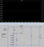
I have modeled the PSU in PSUD2 over several iterations. I have also modeled the entire circuit in LTSpice, although I am still picking up a lot of the functionality of the program, so right now using PSUD2 more for the power supply design.
As far as the PSUD2 models, the only issue I have seen with the supply is a very small amount of low frequency ringing on the output. This can be damped by adding more DC resistance, but like I was saying, I am unsure of the other negative consequences of adding more DC resistance, other than voltage drop since that is not an issue. Robbing Peter to pay Paul maybe?
Right now I am wondering if splitting the PSU rails at the 65uF cap will decrease the crosstalk compared to a single rail for both channels.
Last edited:
Right now I am wondering if splitting the PSU rails at the 65uF cap will decrease the crosstalk compared to a single rail for both channels.
Yes, it would, especially at low frequencies. Of course, you won't hear the decreased crosstalk at low frequencies, at least not directly. Low frequencies spread out quickly from the speakers, and we can't localize them as easily as higher frequencies. But having a separate power supply decoupling branch for each channel of a stereo amp is technically better.
I guess if you have a CLC first psu section, then one LCRC branch for each channel coming off of that...
Or, the reservoir cap after the rectifier, then an LCLC for each channel, so LC to output tube -> LC to driver tube(?).
Code:
       EL34  driver
         |    |
     L1-C1-L3-C3  (left channel)
>|C<
     L2-C2-L4-C4  (right channel)
         |    |
       EL34  driver
I don't know what your driver circuit looks like, but I assume it has two stages (a lower-current voltage amp for input followed by a higher-current driver tube).
--
PS - Your driver circuit won't need a 200mA rated choke will it? You might want to try a 50mA or 100mA rated choke instead in that position (L3 and L4 in the diagram above). That way you can get higher inductance and use nice, smaller value polypropylene psu filter caps for your driver stage. Maybe 15H and 22uF?
L1, L2 = 6H 200mA 100R
L3, L4 = 16H 50mA 550R
or something like that...
--
Last edited:
That is an idea! I had that of that option, the only concern at that point being cramming four chokes inside the chassis. Let me think that over, might be a better approach.
Right now it is just a two-stage amp with the MH4 alone in the driver stage with a 6mA constant current source plate load, then the strapped EL34 output. I was planning to use the fully filtered B+ for both the outputs and the drivers since they are CCS loaded and will then be isolated from the supply.
Any issue with the below design approach, with both the EL34 and CCS loaded MH4 off the final filter caps? Thank you for your help!
P.S. just saw your edits and idea for a higher inductance chokes. I guess my thinking was the power tube would benefit from having two LC filters for very low ripple while the driver stage could basically use whatever was being fed to the power tubes since they are CCS loaded and thus isolated from the power supply. But please let me know if that presents any issues. Am I overlooking something by feeding both stages from the same cap even with the CCS in place?
Right now it is just a two-stage amp with the MH4 alone in the driver stage with a 6mA constant current source plate load, then the strapped EL34 output. I was planning to use the fully filtered B+ for both the outputs and the drivers since they are CCS loaded and will then be isolated from the supply.
Any issue with the below design approach, with both the EL34 and CCS loaded MH4 off the final filter caps? Thank you for your help!
Code:
            EL34
               |
     L1-C1-L3-C2-MH4 w/ CCS (left channel)
>|C<
     L2-C3-L4-C4-MH4 w/ CCS (right channel)
               |
            EL34
P.S. just saw your edits and idea for a higher inductance chokes. I guess my thinking was the power tube would benefit from having two LC filters for very low ripple while the driver stage could basically use whatever was being fed to the power tubes since they are CCS loaded and thus isolated from the power supply. But please let me know if that presents any issues. Am I overlooking something by feeding both stages from the same cap even with the CCS in place?
Last edited:
The driver stage and output stage amplify in opposite polarity. They also have widely different current draw. I think you'd be inviting low frequency instabilities if both are fed from a single LCLC filtered B+ supply. The more conventional way of implementing passive power supply filtering is to decouple stages from each other, using an LC or RC between each stage. You want to remove interactions between the input and output stages through the power supply (some of which can cause 'motorboating').
It seems to me it would be a waste to worry about interactions between the two amplification channels through a common power supply, remove that problem by making a 'dual-mono' power supply, and then introduce a different set of interactions between each output stage and its driver stage by having them fed without decoupling from each channel's leg of the power supply.
I'd say it makes more sense to use your 6H 200mA chokes for the output stages, then use RC decoupling for the driver stages, or use a higher value/lower current choke for the LC decoupling for the driver stage (MH4).
Remember that your 200mA rated chokes will need enough current going through them to be fully energized (yield their rated inductance). A 200mA rated choke with only a 6mA load might buzz (mechanically). That's explained somewhere in Morgan Jones' book.
--
Hey Lordgwyn, sorry I haven't gotten back to you, I have been busy with the holidays and what not.
Here is sort of a block diagram of what I was talking about. If you used a parafeed transformer and a CCS on the output, then you effectively shield the audio path from the power supply.
This allows you to have 1 power supply rail with minimal cross talk.
The obvious problem is the higher voltages and the heat dissipated by the heatsink would be considerable.
However if the problems can be solved, then this approach means that the effects of the power supply on the signal path are minimized and you wouldn't have to worry about filtering as much.
Attachments
The driver stage and output stage amplify in opposite polarity. They also have widely different current draw. I think you'd be inviting low frequency instabilities if both are fed from a single LCLC filtered B+ supply. The more conventional way of implementing passive power supply filtering is to decouple stages from each other, using an LC or RC between each stage. You want to remove interactions between the input and output stages through the power supply (some of which can cause 'motorboating').
It seems to me it would be a waste to worry about interactions between the two amplification channels through a common power supply, remove that problem by making a 'dual-mono' power supply, and then introduce a different set of interactions between each output stage and its driver stage by having them fed without decoupling from each channel's leg of the power supply.
I'd say it makes more sense to use your 6H 200mA chokes for the output stages, then use RC decoupling for the driver stages, or use a higher value/lower current choke for the LC decoupling for the driver stage (MH4).
Remember that your 200mA rated chokes will need enough current going through them to be fully energized (yield their rated inductance). A 200mA rated choke with only a 6mA load might buzz (mechanically). That's explained somewhere in Morgan Jones' book.
--
Hi Rongon - thank you, this makes much more sense to me now, I am going to alter my design with either LC or RC decoupling. I haven't purchased the chokes yet, I might in fact split the rails after the resevoir capacitor as you suggested and use a 15H 100mA 256ohm choke for each power tube LC filter, then a simple RC decoupling for the MH4, will trim some of the bulk, give me better channel separation, more inductance and will energize close to their max rated current (would expect something like 70mA for each EL34). Just an idea, will have to do some modeling, but some variation of this will be in my final design. Thanks for taking the time to explain.
Hey Lordgwyn, sorry I haven't gotten back to you, I have been busy with the holidays and what not.
Here is sort of a block diagram of what I was talking about. If you used a parafeed transformer and a CCS on the output, then you effectively shield the audio path from the power supply.
This allows you to have 1 power supply rail with minimal cross talk.
The obvious problem is the higher voltages and the heat dissipated by the heatsink would be considerable.
However if the problems can be solved, then this approach means that the effects of the power supply on the signal path are minimized and you wouldn't have to worry about filtering as much.
Hey TJ - no worries! I have been busy myself, I am still parsing through through some of the suggestions you made. That is an interesting idea, parafeed output is something I would like to use in the future, but this time around I think I am going to stick to the air-gapped output transformer and rather improve on my power supply design to reduce crosstalk. Obviously there were some glaring issues that I'm now aware of, but hey, better to make mistakes before I start building
.........My understanding is the AC output impedance in a SET amp is roughly equivalent to the ESR of the final cap in the supply, which is 2mOhm....
2 milliOhm seems remarkably small DCR for a tube-amp cap.
The capacitive reactance of 175uFd is *much* more than 0.002r over the audio band (out to 470kHz). As we expect: capacitors are "nearly perfect" over the audio band.
> my first attempt to design my own amp
Do you expect it to be perfect on your first attempt? Is this the last amp you will attempt?
"Own Design" should always include "research", peeping at ALL amplifiers built before. Thousands of commercial designs imply that a fat rail cap is ample decoupling. Yes, hundreds of DIY designs go to town on separation. What to do? Obviously either way works. And a designer preference may evolve over your design career.
3mOhm is the advertised ESR from Clarity Cap on their 175uF 450V TC series. I do not expect it to be perfect, nor do I expect it to be my only attempt, but I would like it to be a good first attempt, so I am seeking the opinions of those with more experience. Thanks for your input
3mOhm is the advertised ESR from Clarity Cap on their 175uF 450V TC series. I do not expect it to be perfect, nor do I expect it to be my only attempt, but I would like it to be a good first attempt, so I am seeking the opinions of those with more experience. Thanks for your input
ESR is in SERIES with the reactance of the capacitor. The two values add together. It is also in series with the AC reactance from the series inductance of the capacitor as well.
Reactance is AC resistance and it is frequency dependent.
The calculation is 1/[2*pi*frequency*capacitance in farads] = reactance.
At 20khz the reactance is very small. For 100uf, I am coming up with 0.09 ohms at 20K. The ESR number is added to this number, so your impedance is actually made WORSE by esr, not better.
At 20hz the situation is even worse. I am coming up with nearly 80 ohms at 20 hz.
So not only is your output impedance much higher than you anticipated, but it actually changes over frequency.
The standard way of handling the situation is to chuck in a very large capacitor to keep the impedance as low as possible, but large capacitors have issues as well. The other solution is some type of regulation, and shunt regulation seems to be the crowd favorite.
Or you know, you could use parafeed since it more or less completely removes the power supply cap from the signal path.
Thanks for the info TJ. The natural next question for me is, at what point does the reactance negatively impact low frequency performance? My original design used a 175uF Clarity Cap, which gives a series reactance of ~45ohm at 20Hz.
Also, if you have any resources on AC/DC power supply output impedance as it relates to designing linear power supplies for audio, I would appreciate it. I'm sure the information is out there, but I have had a hard time finding it, maybe I need to dig deeper into the Radiotron Designer's Handbook.
That's kind of a loaded question because the truth is that any impedance that is non 0 will negatively impact frequency performance.
The question should be whether or not the damage that is done will be somehow objectionable. And the answer is no. In reality, this is a very very VERY small issue. There are far bigger fish to fry like splitting the rails.
Remember that this is a headphone amp. If you don't want to use parafeed, that's totally fine, but now you need to be much more focused on noise reduction than power supply capacitor impedance. One CLC filter before the output stage probably won't cut the ripple down far enough for headphone use.
45 Ohm impedance B+ versus a 4500 Ohm primary impedance is 40 dB of separation (at 20Hz with a 175 uF cap).
That is 60 dB separation at 200 Hz.
If you can find a phono cartridge that has 40 dB of separation at 20Hz, and 60 dB separation at 200Hz,
then you have found a miracle product.
Let us know the cartridge model.
Try and find a record cutter that has that kind of separation.
On the amplifier:
Be sure to keep the two output transformers at a distance from these things:
Power transformer.
B+ Choke.
The other output transformer.
Do not use a steel chassis.
All of these couple magnetically.
Reduce ground loops, especially B+ circuits.
You can reduce the coupling by orienting the windings at right angles.
Think in multiple dimensions, not just left / right, but vertical too.
Failure to observe the above may result in:
Poor channel separation
Hum
Find out what are the outer layers of the onion, and peel them off first.
I'm just sayin'
Last edited:
Just to bring some closure here, after some conversations with other members, I decided to do the following CLCLC design. The MH4 CCS require a higher B+ than the EL34, so come off C2 in the power supply. Then the rails split into two additional LC filters for the EL34. Thank you all for your suggestions and helpfulness.
C1 - 6.8uF
L1 - 6H 200mA
C2 - 100uF
L2/3 15H 100mA
C3/4 - 130uF
Code:
       MH4 (CCS)
         |
         | L2-C3-EL34
>|C1-L1-C2<
         | L3-C4-EL34
         |
       MH4 (CCS)
C1 - 6.8uF
L1 - 6H 200mA
C2 - 100uF
L2/3 15H 100mA
C3/4 - 130uF
- Status
- This old topic is closed. If you want to reopen this topic, contact a moderator using the "Report Post" button.
- Home
- Amplifiers
- Tubes / Valves
- SET Unregulated Power Supply Crosstalk