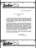
This is the heading of Amber Technical Report 00013 which goes on to explain that the 2 x 32000uF filter capacitors (in their 70 series power amps) require a great deal of energy to charge up, hence the addition of a high voltage 100n cap in parallel with the mains switch. The 100n cap across the switch allows a small trickle of current to keep the filter capacitors slightly charged when the power switch is off.
I've recently seen this in a Conrad Johnson solid state amp. Actually, C-J have opted for an ever higher value, 220n, And the net result is the same, there's always a fraction of a volt present on each main supply rail.
So my question is, as this seems to be an extremely simple and inexpensive soft-start technique, why is it not more extensively used?
4.7 to 10n caps are almost always used for spark suppression, it's rare not to see one, but they're too small to provide the effect the bigger ones do.
220nF (or even 100nF) carries a risk of a shock to the user if wired as you describe. Are there no high voltage rated bleed resistors across the switch/cap ?
Should the unit be unplugged from the mains the cap will be floating at some indeterminate voltage, anywhere from zero to the mains peak depending on the instant the plug was removed. This could be as high as 360 volts in a 'high mains' location in the UK.
0.22 uF charged to that voltage is plenty to give a nasty jolt.
It doesn't sound like good engineering on all counts tbh, both design and the fix needed to overcome a problem.
220nF (or even 100nF) carries a risk of a shock to the user if wired as you describe. Are there no high voltage rated bleed resistors across the switch/cap ?
Should the unit be unplugged from the mains the cap will be floating at some indeterminate voltage, anywhere from zero to the mains peak depending on the instant the plug was removed. This could be as high as 360 volts in a 'high mains' location in the UK.
0.22 uF charged to that voltage is plenty to give a nasty jolt.
It doesn't sound like good engineering on all counts tbh, both design and the fix needed to overcome a problem.
Thanks for the comment, perhaps I didn't explain properly. The cap is across the mains switch (they only switch the live). When the switch is on, the cap is shunted by the switch, so no charge remains. If you turn the switch off, the cap charges again (at which point it is a shock hazard - but so is the switch anyway, by it's nature). If you pull the mains plug at this point, the cap discharges instantly, the charge is consumed by the transformer - yes, even with the switch in the off position (the whole idea of their soft-start). I've just proved it with my scope.
With regard to bleed resistors, yes there is one 4.7K across the combined DC supply (approx 100v). I'm not quite sure why that is relevant. Are you proposing I remove it so that the caps stay charged longer? Ultimately, they will discharge, it's no substitute for a soft start.
The 100nF cap is for spark suppression. Nothing else.
I was just quoting from Amber's technical report. The document carries the name of Cary Lancaster, Director of Engineering. It's one of several, all addressing technical issues. It's in PDF format, I downloaded it from HFE.
Thanks for the comment, perhaps I didn't explain properly. The cap is across the mains switch (they only switch the live).
That's how I read your post
")
When the switch is on, the cap is shunted by the switch, so no charge remains.
Yes, the switch shorts the cap out.
If you turn the switch off, the cap charges again (at which point it is a shock hazard - but so is the switch anyway, by it's nature). If you pull the mains plug at this point, the cap discharges instantly, the charge is consumed by the transformer - yes, even with the switch in the off position (the whole idea of their soft-start). I've just proved it with my scope.
It sounds like there is other circuitry present on the incoming unswitched live side of things then. Otherwise the cap is 'dangling free' and present a shock hazard.
I visualised it like this.

Bleed resistors would have to be on the primary side to affect the cap across the switch.
That's how I read your post
Yes, the switch shorts the cap out.
It sounds like there is other circuitry present on the incoming unswitched live side of things then. Otherwise the cap is 'dangling free' and present a shock hazard.
I visualised it like this.
View attachment 537327
Bleed resistors would have to be on the primary side to affect the cap across the switch.
Yes, you have visualised it correctly and I see what you mean. I didn't see any bleed resistors on the primary side. The incoming live goes through a temp sensing device but it's strictly series. My scope probes were across the cap, that would have completed the circuit with regard to a discharge path....but i't very high impedance. Still, where else can the charge have gone? When you're right, you're right! Round 1 to Mooly
Edit.... and may I add you handled that very nicely. Someone calls your judgement and no snarky comments, just a friendly well reasoned reply. Well done, I think I'm going to like it here
Last edited:
If that report says what you say it says then whoever wrote it should not be allowed near any electronic design. All the cap does is reduce switch arcing at turn off, or perhaps during turn on if the switch suffers badly from bounce. The cap should really be across the mains transformer primary, not the switch, as then it would do exactly the same job but would last longer.
When you're right, you're right! Round 1 to Mooly
Well its just as much the voice of experience. I've been caught too many times by similar set ups in the TV trade, sometimes its a filter cap across L and N before the switch.
And its just waiting to bite the unwary as they wrap the mains lead up
I think a 0.47uF is the worst I've come across on a Japanese set from the 80's. And thanks for the kind words
Thanks.AldoR said:Here is a screen capture of the relevant page, hope it shows up ok...
Errors on that page:
1. What he calls "filter" caps are actually reservoir caps. It is the next set of caps (when present) which actually form a filter.
2. For some reason he puts "charge up" in quotes, as though this isn't what really happens or he is unfamiliar with the term. Charging up is exactly what happens, so no need for quotes.
3. The cap across the switch only has a minor effect on the switch-on surge. The usual solution is a soft-start circuit; there are several ways to do this.
4. It is the current surge at turn-on which creates problems, not voltage surge.
The page is undated; not 1st April by any chance?
Thanks.
Errors on that page:
1. What he calls "filter" caps are actually reservoir caps. It is the next set of caps (when present) which actually form a filter.
2. For some reason he puts "charge up" in quotes, as though this isn't what really happens or he is unfamiliar with the term. Charging up is exactly what happens, so no need for quotes.
3. The cap across the switch only has a minor effect on the switch-on surge. The usual solution is a soft-start circuit; there are several ways to do this.
4. It is the current surge at turn-on which creates problems, not voltage surge.
The page is undated; not 1st April by any chance?
I come in peace
Points 1,2 & 4 are just semantics surely? I include point 4 because I'm sure Cary would agree with you on that one, you can't very well have a voltage surge without the accompanying current surge, they go hand in hand in a situation like this. For what it's worth, I really appreciate your meticulous use of, and approach to, punctuation. From what I've seen on various forums, people are losing their grip on the English language really fast! I'm not an educated man myself, so please pardon my rather unusual style of writing
I happen to have one of these Amber amps. The guy who gave it to me said he bought it in the seventies, no doubt the literature dates back to that era. I couldn't find a date anywhere on the document.
I'm including the following extract for a number of reasons. As you can see, the author also refers to reservoir caps as "filter" caps but what interested me particularly was the reference to magnetic flux and further in, the effect of missing a few mains cycles on toroidals. I would imagine EI transformers are similarly affected?
Anyway my point to all this is, does the 100/220n cap across the mains switch (which allows a voltage to appear across, and a current to flow through) the transformer not partly negate the effect of having to 'recreate' the magnetic flux from scratch?
Sadly, I do not have the benefit of a proper electronics education, so if my question is laughable, please understand. I also don't understand why Rod says "the effect is worst when power is applied as the AC voltage passes through zero". Perhaps you could explain this?
Extract from:
Soft-Start Circuit For Power Amps
Rod Elliott (ESP), Updated 18 April 2006
"When your monster (or not so monster) power amplifier is switched on, the initial current drawn from the mains is many times that even at full power. There are two main reasons for this, as follows ...
Transformers will draw a very heavy current at switch on, until the magnetic flux has stabilised. The effect is worst when power is applied as the AC voltage passes through zero, and is minimised if power is applied at the peak of the AC waveform. This is exactly the opposite to what you might expect
At power on, the filter capacitors are completely discharged, and act as a short circuit for a brief (but possibly destructive) period"
Further in...
"If flaky mains are a 'feature' where you live, then I would suggest that you may need to set up a system where the amplifier is switched off if the mains fails for more than a few cycles at a time. The AC supply to a toroidal transformer only has to 'go missing' for a few cycles to cause a substantial inrush current, so care is needed."
Lastly, your point 3.
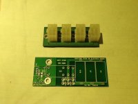
I'm aware that there are other ways to soft-start a power supply. I opted for a relay shunting out a bunch of resistors in this particular design. The board is double sided and was intended to carry parallel 5w devices on both sides if necessary. There was a 'smarter' version 2 but I can't find it right now.
Attachments
Last edited:
Words have meanings. Using them to mean something else hinders communication, and may indicate lack of understanding.AldoR said:Points 1,2 & 4 are just semantics surely?
For some reason it has become popular to refer to the reservoir caps as 'filter' caps, but their action is not one of filtering.
If you suddenly attach an inductor (e.g. a transformer) to an AC sine wave source then the initial current surge is maximised if you attach at the time of the AC zero crossing. To understand why you would need to go through the theory and do the maths, which requires some calculus. This is because the current through an inductor does not depend on the voltage across it (unlike a resistor) but instead on the integral of all the voltage which has ever been across it.
If that report says what you say it says then whoever wrote it should not be allowed near any electronic design. All the cap does is reduce switch arcing at turn off, or perhaps during turn on if the switch suffers badly from bounce. The cap should really be across the mains transformer primary, not the switch, as then it would do exactly the same job but would last longer.
I agree, it doesn't make sense. Sometimes you see 'tech' people publish things that aren't quite right as a sort of marketing effort, but here I can't even see that advantage.
Intriguing.
Jan
Words have meanings. Using them to mean something else hinders communication, and may indicate lack of understanding.
For some reason it has become popular to refer to the reservoir caps as 'filter' caps, but their action is not one of filtering.
If you suddenly attach an inductor (e.g. a transformer) to an AC sine wave source then the initial current surge is maximised if you attach at the time of the AC zero crossing. To understand why you would need to go through the theory and do the maths, which requires some calculus. This is because the current through an inductor does not depend on the voltage across it (unlike a resistor) but instead on the integral of all the voltage which has ever been across it.
I agree completely, and it's good that you try and maintain a standard. You may find the link below interesting. I was saddened to read it especially as it was authored by a lecturer in linguistics. However, some of the first reader comments highlight the importance of what you say.
https://theconversation.com/what-grammar-pedants-and-fashion-victims-have-in-common-55248
Thank you for the explanation regarding the inductor. I'm not likely to be able to manage the maths but will read up on it regardless. It's a most interesting concept.
I agree, it doesn't make sense. Sometimes you see 'tech' people publish things that aren't quite right as a sort of marketing effort, but here I can't even see that advantage.
Intriguing.
Jan
Jan, the biggest drawback I can see is the one Mooly pointed out. That under certain conditions the set presents a shock hazard. On those grounds alone it would probably be illegal today. That could also answer my original question. Having said that, we have established that the cap will provide a reduction in initial inrush current, albeit a small one.
Looking at it from Ambers perspective, they were able to come up with a one component fix, for a problem they were having. I'd take it as a given that they tested their solution in their R&D facility before dashing off a service bulletin to the masses. That they make reference to a partly lit power indicator is evidence of this.
That was 40 years ago. 20 years later, Conrad Johnson are doing the same thing on at least one of their power amps. Why? You don't need 220n for spark suppression. 4.7 to 10n seems to be the industry standard. Going back to the potential shock hazard, I understand now why the CJ cap was wearing a sort of half rubber/plastic boot. It only covered the left side (what would be the hot side) of the cap in a switched off situation. I guess they didn't anticipate anyone being zapped by the plug itself
What if you just put a 1M ohm R across the cap, that is across the switch? Won't that fix it? A 100n will then discharge in less than half a second. I noticed that Linkwitz put a 1M ohm R across the primary of a toroid power tranny in his pluto circuit. Apparenly to discharge the toroid. I never realized there was a potential shock hazard there in either place. Thx for the info.
What if you just put a 1M ohm R across the cap, that is across the switch? Won't that fix it?
It would remove the shock hazard but the resistor would have to be specified for 24/7 use at the intended voltage.
All this (the problem and the manufacturer solution) smacks of poor engineering to me.
Also, this talk of the power indicator glowing all the time would drive me nutz
Ferguson 1400 and 1500 series black and white TV did that, the 1600 had a 4M7 bleed resistor. Ouch!Well its just as much the voice of experience. I've been caught too many times by similar set ups in the TV trade, sometimes its a filter cap across L and N before the switch.
And its just waiting to bite the unwary as they wrap the mains lead up
And thanks for the kind words
- Status
- This old topic is closed. If you want to reopen this topic, contact a moderator using the "Report Post" button.
- Home
- Amplifiers
- Solid State
- S-70: Turn-On Shock Reduction