Hi Guys,
I wish to implement a balanced digital output on a CD Player that I'm using as a transport only. The reason for using balanced put is that I do not want to modify the receiver in the processor its being connected to.
Currently the player has the normal TOS and SP/DIF outputs.
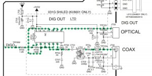
My thinking was to bypass the buffer logic as I'll only be driving the 1 balanced output (other outputs will be isolated) but retain the filtering and output transformer. I'll also change the series 75ohm to 110ohm as I believe this is what is used to set the output impedance.
Any reason this should not work? Thanks in advance for your comments.
Ian
I wish to implement a balanced digital output on a CD Player that I'm using as a transport only. The reason for using balanced put is that I do not want to modify the receiver in the processor its being connected to.
Currently the player has the normal TOS and SP/DIF outputs.
My thinking was to bypass the buffer logic as I'll only be driving the 1 balanced output (other outputs will be isolated) but retain the filtering and output transformer. I'll also change the series 75ohm to 110ohm as I believe this is what is used to set the output impedance.
Any reason this should not work? Thanks in advance for your comments.
Ian
Attachments
Any reason this should not work?
I can see one obvious one - the 1k2 resistor you now have in series with the trafo primary. The buffer you deleted was there for a reason - providing drive capability.
I can see one obvious one - the 1k2 resistor you now have in series with the trafo primary. The buffer you deleted was there for a reason - providing drive capability.
That's fine, I can leave the logic in the circuit. I only removed as I thought it may have only been there to provide the drive to the original multiple outputs.
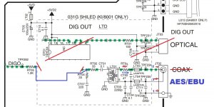
How does this look? As much as anything, I'm interested in the change from the 75r to 110r in series with the output side of the transformer.
Attachments
My main concern is the voltage levels you need - according to AES/EBU spec the minimum signal is 2V p-p, whereas S/PDIF is only 0.5V. So if your aim is to meet the spec somehow you'll need 4X as much signal. Without a spec for the transformer I'm not clear that it can support this.
Chances are it will still work with 0.5V as the spec for the receiver says it should operate with down to 0.2V, but then you'll have no noise immunity so the slightest interference will likely cause it to lose lock.
Do you have any details on the transformer?
Chances are it will still work with 0.5V as the spec for the receiver says it should operate with down to 0.2V, but then you'll have no noise immunity so the slightest interference will likely cause it to lose lock.
Do you have any details on the transformer?
The Player is a Marantz SA7001.
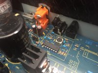
The part is listed as TPS247MN-0386AN PULSE TRNSF. and I cannot find any data on the part. Pic attached.
I am playing with Digital EQ (for room correction and low level listening) and have inserted a Behringer DEQ2496 between the marantz as a transport and my Audio Aero Capitole MKII which I'm using as the DAC.
Interestingly, there is no difference on the Aero's input circuitry between, SPDIF, BNC and AES/EBU so I guess it will work as you say even with the 0.5v p-p.
Are there any AES/EBU specific balanced driver logic devices (or even just 2v p-p logic buffers) that would be better suited here? The cable run will be approx 0.75m between the DC player and the DEQ processor but I'd like to implement the new output to correctly even it it will (most likely!) work with the 0.5v p-p output.
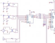
I've attached the Aero input schema for reference. U4 is a DS3486M and R15,16, 30 & 31 are all 75r!!! T1,2 & 4 are identical parts which I beleive to be 1:1 isolation transformers. Not sure why we have a 75r on the balanced input??
The part is listed as TPS247MN-0386AN PULSE TRNSF. and I cannot find any data on the part. Pic attached.
I am playing with Digital EQ (for room correction and low level listening) and have inserted a Behringer DEQ2496 between the marantz as a transport and my Audio Aero Capitole MKII which I'm using as the DAC.
Interestingly, there is no difference on the Aero's input circuitry between, SPDIF, BNC and AES/EBU so I guess it will work as you say even with the 0.5v p-p.
Are there any AES/EBU specific balanced driver logic devices (or even just 2v p-p logic buffers) that would be better suited here? The cable run will be approx 0.75m between the DC player and the DEQ processor but I'd like to implement the new output to correctly even it it will (most likely!) work with the 0.5v p-p output.
I've attached the Aero input schema for reference. U4 is a DS3486M and R15,16, 30 & 31 are all 75r!!! T1,2 & 4 are identical parts which I beleive to be 1:1 isolation transformers. Not sure why we have a 75r on the balanced input??
Attachments
No point in modifying the output impedance to 110R if you know the termination's going to be 75R.
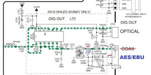
I think just try it with the current arrangement because on looking more carefully I see no input side attenuator between trafo primary and HC04 inverters. So perhaps its already being driven above the S/PDIF spec.
If you want to 'gild the lily' and get even more output you can re-purpose the HC04 sections which were originally driving the TOSLINK output. You'll want to parallel two HC04 inverters (just as shown for pins 3-6) and feed their input from pin6. That'll create an anti-phase signal which can be fed to the currently grounded pin on the trafo primary. We're taking a punt here that the trafo can handle double the Vs.
Last edited:
No point in modifying the output impedance to 110R if you know the termination's going to be 75R.
Thats in the Aero but I've no idea what it will be in the DEQ2496 which is what the CDP will connect to.
I can only assume
 that the correct termination exists in the DEQ as there is virtually no service data available.
I think just try it with the current arrangement because on looking more carefully I see no input side attenuator between trafo primary and HC04 inverters. So perhaps its already being driven above the S/PDIF spec.
If you want to 'gild the lily' and get even more output you can re-purpose the HC04 sections which were originally driving the TOSLINK output. You'll want to parallel two HC04 inverters (just as shown for pins 3-6) and feed their input from pin6. That'll create an anti-phase signal which can be fed to the currently grounded pin on the trafo primary. We're taking a punt here that the trafo can handle double the Vs.
Yep so disconnect the Gnd from the input side of the transformer and run it from a signal 180 deg out of phase via the repurposed buffer. That would at least double the p-p voltage. Sound interesting
Anybody have any commercial circuits that output correctly via AES/EBU from a single ended dac/decoder chip.
The Player is a Marantz SA7001.
The part is listed as TPS247MN-0386AN PULSE TRNSF. and I cannot find any data on the part. Pic attached.
I am playing with Digital EQ (for room correction and low level listening) and have inserted a Behringer DEQ2496 between the marantz as a transport and my Audio Aero Capitole MKII which I'm using as the DAC.
Interestingly, there is no difference on the Aero's input circuitry between, SPDIF, BNC and AES/EBU so I guess it will work as you say even with the 0.5v p-p.
Are there any AES/EBU specific balanced driver logic devices (or even just 2v p-p logic buffers) that would be better suited here? The cable run will be approx 0.75m between the DC player and the DEQ processor but I'd like to implement the new output to correctly even it it will (most likely!) work with the 0.5v p-p output.
I've attached the Aero input schema for reference. U4 is a DS3486M and R15,16, 30 & 31 are all 75r!!! T1,2 & 4 are identical parts which I beleive to be 1:1 isolation transformers. Not sure why we have a 75r on the balanced input??
Hello UV101,
I have a Marantz CD-7300 and the previous owner fried the pulse transformer mounted before coaxial output, the same part you mentioned above, TPS247MN-0386AN PULSE TRNSF. On my fried pulse transformer the primary winding has 1,7 ohm and the secondary winding has just 0,2 ohm. Since transforming ratio should be 1:1, I guess he accidentally connected some voltage (syncro remote cable) on coaxial output by mistake and the secondary winding boiled and perhaps affected the primary winding, too.
I need this part and if you concluded your project with AES/EBU and if this pulse transformer has no use to you now, I'll rather buy it from you, since I cannot find it in Marantz network. I'll pay in advance all the costs, including shipping.
If you do not want to sell it please tell me what is the resistance on primary and secondary winding? I'll try to find a close replacement.
Waiting for your feedback on this.
Thanks in advance!
- Status
- This old topic is closed. If you want to reopen this topic, contact a moderator using the "Report Post" button.
- Home
- Source & Line
- Digital Line Level
- Replace SPDIF with AES/SBU balanced output