Hello. I've been trying to figure out PSUD2 for designing tube amp power supplies for some time now, and I am confused about the results that I get. Specifically, when I plug in the component values of a known circuit, the voltages displayed in PSUD2 are not the actual values measureable in circuit. I know from reading about other peoples use of the program that I am probably overlooking something obvious, but there isn't really a guide that helps me understand what it is that I'm missing. I have read DHTROB's guide and many posts here and elsewhere without an answer. For example, Decware makes available online their power supply design for the SE84CS, and the power supply test points that should correspond to that circuit. The posted voltages and the PSUD2 voltages do not correspond. Any advice would be greatly appreciated.
The test points for the SE84CS and schematic for the power supply are found here Zen Triode Amplifier Kit Assembly Instructions If the component values are put into PSUD2, the voltages shown by PSUD2 are all substantially higher than those indicated on the Decware site. I'm not sure if it is OK to post a screenshot of the Decware page here, so I haven't. When I put the component values into PSUD2, I get the following:
A 400 instead of 365 at V(C1)
B 396 instead of 283 at V(C2) B+ to OPTS comes off this capacitor
C 349 instead of 250 at V(C3)
D 317 instead of 225 at V(C4)
Am I missing the inclusion of a current trap? If so, how is this used in PSUD2?
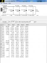
This is a screenshot of my PSUD2 result.....
A 400 instead of 365 at V(C1)
B 396 instead of 283 at V(C2) B+ to OPTS comes off this capacitor
C 349 instead of 250 at V(C3)
D 317 instead of 225 at V(C4)
Am I missing the inclusion of a current trap? If so, how is this used in PSUD2?
This is a screenshot of my PSUD2 result.....
Attachments
Thanks DF96. I think I figured it out. This circuit uses two EL84s. The B+ comes off of the second 40UF capacitor to the OPTs and then to the EL84s. If I understand it correctly, that means that I should place a current draw after the second capacitor to represent the draw of the EL84s. Is that correct? How do I account for the OPTs? The 3.3uF capacitor feeds the preamp tube through a 47k resistor. How is that represented in PSUD2? I have a 47k resistor in my example at the end of the chain, but I'm not sure if that is the right way to do it, or if I should be using the constant current option instead with the draw of the preamp tube instead. Also, I'm not clear on how to add several current draws at different nodes to one simulation with respect to their cumulative effect. Do I put in the expected current draw of the power tubes and pre tubes at C2 in my example, or do I put in the draw of just the power tubes and put in a seperate current tap for the preamp tubes at C4? Thanks again in advance for any advice that you provide.
The only thing you can do in PSUD2 is to place loads at the tap off points in the power supply. You don't need to "account" for the OPT. If you know the cathode current for each tube the OPT is in series and has the same current. Its the same with the other circuits. If you know the current in a stage just attach that value load in PUSD2.
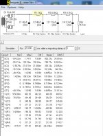
Oops. This is the correct screenshot.....
What does the "2Ω" relate to in the filter caps? Is this the series resistance of the capacitors? If so, that should be quite a bit higher, I guess.
I think that the 2ohm is the resistance that the actual capacitor has. I just left it at what PSUD2 sets it to. It does make a small difference to the results you get, but I haven't looked at the actual capacitor values in order to put in the correct ohm value for the caps.
- Status
- This old topic is closed. If you want to reopen this topic, contact a moderator using the "Report Post" button.
- Home
- Amplifiers
- Power Supplies
- PSUD2 Help