I was reading the thread about using split load op amps to drive a push pull stage. That thread drifted onto the subject of protecting OPTs. which I'm very interested in. Rather than further drive that thread off the original subject, which I'm nonetheless interested in, I'll continue the thread about protecting OPTs here.
I'm in the process of designing an amp that borrows concepts from various places. Unfortunately when you do that sometimes those concepts don't play nice with each other. Tubelab brought up some very good points in that thread. I'm using a Plitron cathode feedback OPT in the design, not the unity gain one, so I can't use cap bypassed resistors to auto bias. If I did it would negate the CFB in the OPT and hold the dynamic as well as static signal in the cathodes at a constant level.
Since the OPT is so expensive I really want to protect them. Tubelab opened my eyes to the fact that if I fuse the cathodes at a common point then when it opens due to overcurrent it will cause a big spark that might destroy the OPT. I'm really concerned about that now. I'm planning on using mosfet source followers to drive the final in AB2 bias. My understanding is that eliminates the use of CCS's in the cathode circuits in the final stage.
My question is this then: what would be the best way to protect the circuit. I generally go for the simplest answer so I'm not looking for something complicated. Just as long as it doesn't affect the sound. Any help is appreciated. Thanks much.
http://plitron.com/wp-content/uploads/file/2100CFB.pdf
This one has only 10% signal feedback, not 100% like the unity gain model. There's two other models similar to what I ordered in their specialist line. The reason I went for the 10% feedback one is it doesn't require the driver capability of the unity gain.
This one has only 10% signal feedback, not 100% like the unity gain model. There's two other models similar to what I ordered in their specialist line. The reason I went for the 10% feedback one is it doesn't require the driver capability of the unity gain.
I suspect that a metal oxide varistor (MOV) is the best answer here.
My only concern would be if it loads the circuit before it reaches its breakdown voltage, especially if it is a non-linear load.
It would be easy enough to put it in there, get the amp working, and then take distortion measurements with it in and out of circuit to see if it adds any ugliness.
I'm guessing here that the best place to position a MOV would be between B+ and ground to protect the OPT. I suppose you would use it in conjunction with a permanent fusing device. Otherwise it might end up in an endless cycle of field collapse and regeneration.
The problem (at least to these eyes) is that if this combination of fuse and transient suppression was a good solution in the final stage of a tube amp then why isn't it a standard practice? I'm sure this problem crops up all the time in non-self biased amps. Does it affect the sound I wondering? This would also apply to gas discharge tubes. I'm really in way over my pay grade here and have no experience whatsoever.
The problem (at least to these eyes) is that if this combination of fuse and transient suppression was a good solution in the final stage of a tube amp then why isn't it a standard practice? I'm sure this problem crops up all the time in non-self biased amps. Does it affect the sound I wondering? This would also apply to gas discharge tubes. I'm really in way over my pay grade here and have no experience whatsoever.
http://plitron.com/wp-content/uploads/file/2100CFB.pdf
This one has only 10% signal feedback, not 100% like the unity gain model. There's two other models similar to what I ordered in their specialist line. The reason I went for the 10% feedback one is it doesn't require the driver capability of the unity gain.
Okay, so you do have separate CFB windings for each tube. My protection circuit is very simple compared to what tubelab was describing for his dream amp.
I have current-sense resistors under each CFB winding, between the winding and ground. I use those for two purposes.
One is a bias servo. I bought the one from Guido Tent and it works great. I had originally designed one, had the cheapest place I could find fab it, only to find that the boards were bad. I then threw money at the problem to get it done.
The second goes to the monitor circuit. I take that signal from the current-sense resistors and also filter it and send it to a comparator that goes high if a reference voltage is crossed. That goes into a microprocessor board that monitors two things, the output of the comparators and the on/off switch. Either of those can cause the amp to shut off. The microprocessor controls power-up/power-down via solid state relays on the transformer primaries.
I recognized that in my design I am putting a lot of trust in the bias servo. That thing has the power to kill my power tubes and output transformers if it wants to. I designed the monitor circuit to put a check on that power.
The concern about distortion increase might be valid. It should be tested, if someone hasn't done this already. Protection against high voltage transients could be achieved with an MOV connected across any winding of a tightly coupled transformer, so it would make sense to use the cathode winding or secondary for this purpose. Loudspeaker loads certainly act to suppress transients and probably save most OPTs from damage in misbehaving hi-fi amps.
I would be concerned about capacitance of MOV devices. Especially if it is varying with V. Presumably the datasheet would have this info. I've got some MOVs here somewhere. I'll check one on the C meter.
I just checked a 175L10 (probably 175V rating) and its got 836 pf on the meter. That would spoil most OT HF responses.
Idea: Use a HV Mosfet across the B+ to plate winding on each side of the OT with a series HV diode (Source at one end, then to Drain and diode at the other). Put voltage divider resistors across the Drain to Source, with the mid-point going to the gate. Scale the divider so it turns on the Mosfet at some given HV across the Mosfet. You could put them in both polarities on each side of the OT. The HV diodes prevent them from conducting when reverse polarity. One could get more accurate firing V using a trigger diode, like used for SCR firing.
Last edited:
I would be concerned about capacitance of MOV devices. Especially if it is varying with V. Presumably the datasheet would have this info. I've got some MOVs here somewhere. I'll check one on the C meter.
I just checked a 175L10 (probably 175V rating) and its got 836 pf on the meter. That would spoil most OT HF responses.
Unfortunately the hard drive died on my computer that had the LT Spice model of my circuit.
 Luckily I've got a printed copy of it. If I still had a working LT Spice model I'd just plug in capacitor values one at a time across different windings of the OPT and see what it simulates as an output. Now that's out the window. Of course, that doesn't model varying individual capacitances but one might get a pretty good idea by just plugging in a range of different cap values at each individual position. To bad I can't do it now.
trobbins seems to have experience with MOVs: http://www.diyaudio.com/forums/tubes-valves/180744-tube-output-protection.html
I should have known that someone here would have already investigated solutions to this problem in depth. I'm only a little way through reading everything to do with that thread but can already see that the answers are there. What an incredible resource we all have here. Thanks spreadspectrum, and especially to you, trobbins, if you are out there.
As stated, but often misunderstood, there are two modes of OPT destruction. Over voltage, as I described in the other thread, and over current....a bad output tube that has runaway, and the red glow has turned to a tube arc.
As stated the overcurrent failure can be solved with a fuse in the B+, IF the fuse and fuseholder is rated for the B+ voltage. DC will arc, and an arc that happens inside a fuse will cause it to violently explode......Trust me, DON'T use a 250 volt glass fuse in a 500 volt B+ circuit. The bang alone will scare you to death.
The voltage caused by an unloaded, or misloaded amp is a different story. There have been all sorts of different methods to protect OPT's from destruction, with varying results.
The diode from Plate to ground, or plate to B+ works reasonably well on amps that rarely see clipping, but become sonically obvious when clipping happens.
MOV's can work if sized properly. MOV's fail to a short! Sometimes a flaming short.
Transient protection diodes (Transorb's) are specialized zeners designed to stop high voltage transients on a lower voltage line. They are available up to 500 volts or so.
Gas discharge tubes (GDT's) are yet another weapon in the war against transients.
About 20 years ago I worked in a think tank environment as a problem solver. I spent 6 months redesigning two products to resolve field failures due to lightning. I simulated lightning strikes with a medical defibrillator, and found that each case responded to a different combination of the above devices depending on the application, circuit inductance, capacitance, and PCB layout.
The GDT can eat the biggest transient without damage, but repeated hits will quickly raise its internal temperature leading to an arc.
I have not spent much time playing with these devices since the "home made lightning" days, but I would start with a GDT across each half primary, a resistor (say 50 to 100 ohms 20 watts or more) across the speaker terminals with a MOV, Transorb, MOV or some combination in parallel.
The GDT emits a very visible flash of light when it fires, so I may look at sensing that and shutting down the amp, or reducing its output if there are repeated "events."
I am looking at an amp that runs a B+ in the 650 volt range and puts out 400 to 500 watts. I have several smallish OPT's that have seen this B+ voltage without failure even though they were designed for about 400 volts. I will not trust the Plitrons in an amp until I can protect the little OPT's from a disconnected speaker at full power. Note, it was one of these same OPT's that burst into flames when my load resistor blew several years ago.
GDT:
http://media.digikey.com/pdf/Data Sheets/Epcos PDFs/B88069X3880T502.pdf
Transorb:
http://www.littelfuse.com/~/media/e.../littelfuse_tvs_diode_1_5ke_datasheet.pdf.pdf
One problem I'm having is drilling down into specifying the component values for either an MOV or GDT. One thing I'm noticing is that I may have a problem using a MOV on the secondary. The lower voltage MOVs have a pretty high capacitance - up to 1nf. I'd like to avoid that if possible unless I can incorporate it with a zobel. That's something I'm really not up to speed in doing so would like to avoid it. As far as MOVs failing in shorted conditions... Well, I'm willing to sacrifice one as long as a fast blowing fuse in the cathode circuit is the primary failure mode.
I may be thinking about this wrong (I've done that before) but wouldn't most of the energy of the field be in the primary? If you shorted a high voltage transient spike with a MOV it seems like most of the energy would be dissipated in the primary. Perhaps a resistance in series with the MOV would stop the field from collapsing too fast and causing secondary catastrophic damage. I'm not up to speed on MOVs to know if a secondary series resistance would be necessary. Trobbins seems to think they have fairly gentle shorting characteristics, unless I misinterpreted him.
So right now I'm thinking of this:
1. Fairly low capacitance high voltage MOV between the B+ and ground.
2. A fast blow cathode fuse bypassed with a resistance high enough to bias the tubes off if the fuse blows.
3. A high voltage fuse in the ground return line of the B+ before diode rectification. That should eliminate shorts in the fuse itself after it blows.
I'm sure there is something I haven't reasoned out here. That's what I'm depending on you all for.
Edit: when I said a "secondary series resistance" I just meant a resistor in series with the MOV, all in parallel with the primary side of the OPT.
Last edited:
Spark plug across the primary?
A GDT is a specialized spark plug. It is more like gas voltage regulator tube with some avalanche properties.
The device I looked at in the linked data sheet is essentially a 1 pF capacitor as long as it sees less than 1000 VDC, or a 1200 to 1400 volt transient, depending on the rise time. When the breakdown voltage is reached a "glow discharge" event occurs (similar to a gas regulator or a neon lamp). Like the regulators, the glow discharge will "regulate" (clamp the voltage) to 180 volts, as long as the transient current does not reach approximately 1 amp. When the transient voltage drops below 180 volts, the glow extinguishes and the device returns to its "1 pF cap mode." This is the normal mode of operation. A transient will fire the device, and be clamped to 180 volts, the device will extinguish on the next AC transition through zero volts.
If the transient current did go over 1 amp, the device will transition to the "arc" region, where the gas glow inside becomes a plasma arc, and the device no longer "regulates." At 1 amp, the voltage drop is about 20 volts. There are current limitations that must be respected to avoid melted or exploded devices. This tube is designed to operate directly across the 240 volt line voltage. The primary fuse must blow within 1 second if the current is less than 10 amps on 50Hz. and less than 9 AC cycles at 50 Hz if the current is above 65 amps.
These devices were originally developed to clamp transients on wire line phone circuits where the current was limited by wiring resistance, and the maximum ringer voltage was about 90 volts. 20 years ago, devices to operate directly across the US spec 120 volt line voltage were available, and we used them. The vendor had just qualified a new device specified for use across the US spec 240 volt 60 Hz power line. We demonstrated to them that under normal operation they could be made to burst into flames, and the devices were withdrawn from the market. 20 years have gone by, and there are lots of new devices made for 240 volt use today.
?but wouldn't most of the energy of the field be in the primary
The energy is temporarily stored in the core's magnetic field, which should induce a rising voltage in all windings as the current flow is interrupted. There are far more turns on the primary, so this is where the fastest rising voltage will be found. The quality of the OPT will determine how well the coupling between the windings is. I do believe that limiting the primary voltage is the best way to avoid OPT failure. However, in theory the energy held in the collapsing field can be safely dissipated in any winding.
Consider an automotive ignition coil. The core is "charged" by forcing a current through the primary. This current is abruptly interrupted by the breaker points, or a silicon device, causing the field to collapse, which induces a multi kilovolt spike in the secondary. Note that the small gap (usually .040 inch) in the spark plug becomes effectively much wider when 10 atmospheres of non conductive fuel / air mixture is squeezed into the gap. It's effectively about 3/4 inch.
1. Fairly low capacitance high voltage MOV between the B+ and ground.
NO, the B+ is already bypassed to ground for AC due to the filter capacitance in the power supply. If the OPT produced a transient between the B+ terminal and ground, it would safely be absorbed by the power supply. Whatever action taken must be applied directly across one or more windings in the OPT. I have seen diodes connected between the output tube plates and ground. This usually helps, but silicon usually fails to a short, so this would connect B+ directly across the OPT half primary, not a good idea.
2. A fast blow cathode fuse bypassed with a resistance high enough to bias the tubes off if the fuse blows.
Good idea, make sure the cathode bypass capacitor (if cathode biased) is rated higher than the tubes cutoff voltage.
3. A high voltage fuse in the ground return line of the B+ before diode rectification. That should eliminate shorts in the fuse itself after it blows.
I assume you mean in the CT of the power transformer. This is a good idea, but all the stored energy in the filter caps must go somewhere if there is a short. The usual path is through the OPT. A dead shorted tube, is however rare, but I have seen it happen. I had one of the early Chinese KT88's (20 years ago) spark out so bad that the glass shattered. Even still nothing else blew up. I replaced the tube and all was well. It was a guitar amp, and I was abusing it a bit.
I would place the main transient absorber directly across each half primary (plate to B+) with the "helper" device(s) on the speaker winding. My thoughts lean toward the GDT in the linked data sheet, or 2 lower voltage devices in series across each half primary. Adding 1/2 to 1 pF here would not be noticed. Experimentation is needed to find a GDT (or pair of GDT's) that would not fire under the normal abuse of a guitar being played through the amp at full crank, yet be able to catch damaging transients.
Adding even a fixed resistor across the speaker terminals goes a long way to reduce the peak voltage in the case of a total open circuit load.
A Transorb diode or a MOV can be added, but as stated both appear as a large nonlinear capacitor across the speaker. Not sure yet which would have less audibility, a big one across the speaker, or a smaller one across the primary. Low voltage GDT's are available with the same 1pF capacitance, but I don't know how well they will work across the speaker leads of a 500 watt amp.
George,
Thanks a lot for the information. By happenstance, (sometimes these things seem like more than that), the B+ voltage planned for will be 335volts. 240vrms times 1.41 = 338vdc. You nailed it! So since 1 pf is a lot better than 100pf or so I'll go with one of those 240volt gdts across each side of the primary. I'm not inclined to add anything similar on the secondary just to avoid excess intrusion. I may add a high wattage resistor across the speaker terminals. Or not. This is going into a hifi amp and I think the only danger of the speaker disconnecting is during construction when I'm using a dummy load instead. I'll have to think about it. Otherwise I think I'll stick with the original plan except for the advice to use a 240volt GDT across each side of the primary.
Thanks!
Last edited:
George, in case you're wondering why such a low voltage B+ on a 100 watt rated OPT... it will be using paralleled small output tubes, ie. el84 and/or 6v6. That way I can get away with using a single 6sn7 driver/cathodyne pair to drive it. It simmed at 60 watts on LTspice using just 2 el84s per side, 4 el84/channel using your source follower design. The cathodyne setup using a single stage of amplification is a bit of an experiment, but that stage sims such a clean signal out that I'm betting the final stage cathode feedback of the Plitron will supply all the feedback I need. Yeah, it's a bit of overkill using that OPT. But more is better as they say.
Last edited:
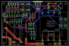
Hey this is topical. I am working this up. It watches up to 4 tubes using the 1.024 volt A/D reference voltage on a PIC 16F1825. The program works in tube pairs and watches for a 20% imbalance between two push-pull tubes and shuts down if it finds it.
So for say a 60mA bias using a 5 ohm cathode resistor gives .3 volts to the A/D converter of the PIC. I also programmed it to shut down at 1 volt for any tube or 200mA using a 5 ohm resistor. So far in testing it is working great.
So for say a 60mA bias using a 5 ohm cathode resistor gives .3 volts to the A/D converter of the PIC. I also programmed it to shut down at 1 volt for any tube or 200mA using a 5 ohm resistor. So far in testing it is working great.
Attachments
Hey this is topical. I am working this up. It watches up to 4 tubes using the 1.024 volt A/D reference voltage on a PIC 16F1825. The program works in tube pairs and watches for a 20% imbalance between two push-pull tubes and shuts down if it finds it.
So for say a 60mA bias using a 5 ohm cathode resistor gives .3 volts to the A/D converter of the PIC. I also programmed it to shut down at 1 volt for any tube or 200mA using a 5 ohm resistor. So far in testing it is working great.
Interesting. Right now I'm working on making the disparate ideas I already have on my plate play nice with each other. I'm not really concerned at this point in refining current balance with a microprocessor. Provisions are already made for individual manual bias control for each tube via a dedicated source follower mosfet. Overall balance of each side of the push-pull for each channel will be front panel accessible without changing each tube's individual bias adjustment. Two meters on the front for that. I'm old school that way. I'm also a believer that when you explore new territory then it behooves you to be as conservative as possible in every other aspect.
Despite my own preferences I hope you can get it to work reliably for you. I'm sure there are many members here that would be interested in what you are doing.
Last edited:
- Status
- This old topic is closed. If you want to reopen this topic, contact a moderator using the "Report Post" button.
- Home
- Amplifiers
- Tubes / Valves
- Protecting Plitron OPT