I created this schematic:
http://img607.imageshack.us/img607/6003/fotoeb.jpg
I cant use the [img... Tag because the picture is too big.
Will it work? Its my first design, so I´m not really sure")
All Ideas are welcome!
Greetings Xiider
http://img607.imageshack.us/img607/6003/fotoeb.jpg
I cant use the [img... Tag because the picture is too big.
Will it work? Its my first design, so I´m not really sure
All Ideas are welcome!
Greetings Xiider
Redesign. Decide what you want to achieve, then design a circuit to do it.
You could reduce the gain and distortion by replacing the cathode LED with an unbypassed resistor. Snag is that this will raise the output impedance.
You could add anode-grid feedback, to turn it into an anode-follower. This will reduce output impedance, but also reduce input impedance.
You could reduce the gain and distortion by replacing the cathode LED with an unbypassed resistor. Snag is that this will raise the output impedance.
You could add anode-grid feedback, to turn it into an anode-follower. This will reduce output impedance, but also reduce input impedance.
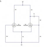
A little generic preamplifier stage
DF96 said it best. Design circuits FOR a purpose, WITH ideals-of-performance as the driving factor.
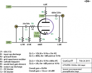
For instance - (taking my own advice) - I just cooked this up for your dining pleasure: A 12BZ7 version of a decent first stage.
DF96 said it best. Design circuits FOR a purpose, WITH ideals-of-performance as the driving factor.
For instance - (taking my own advice) - I just cooked this up for your dining pleasure: A 12BZ7 version of a decent first stage.
Attachments

Working with the 6J6 data spec pages...
Gain is lower, operating point similar, 5 ma running current. Gotta watch that 6.8K anode resistor: P = E^2 / R = 30 x 30 / 6800 = 1/4 watt. But if you choose a lower plate voltage (say, 100V instead of my 150V), then the voltage across it is now 80 volts, so P = 80 x 80 / 16,000 = nearly one HALF watt. Bigger resistor, of course.
Same goes for the use of higher B+ voltages (to increase gain mostly). Just make certain you do the power-dissipation calc for the poor anode resistor. Its the one taking the brunt.
ATTACHED is the modified drawing, with typos fixed.
GoatGuy
Attachments
I generally find a reasonable starting point to be the one listed in the "Class A1 Amplifier" section of the data sheet for the tube. Google/Bing "TDSL" (Tube DataSheet Locator) and you shall find...
6J6 datasheet: http://www.mif.pg.gda.pl/homepages/frank/sheets/093/6/6J6.pdf
You'll notice the anode voltage being 100 V, plate/anode load resistor 7100 ohm, plate current 8.5 mA, and the cathode bias resistor being 50 ohm.
Nearest standard values for the resistors would be 6.8 kOhm and 51 ohm. Calculate the needed B+ voltage from the anode resistor using Ohm's law: B+ = 100 + 6800*0.0085 = 158 V.
Looking at the plate curves, I'd personally prefer an operating point that would allow for more signal swing on the grid. Using a 5 mA CCS and a red LED (HLMP-D101 for example) with a 1.7 V drop, would be a good starting point. You should be able to get a gain of 30-something out of that.
~Tom
Last edited:
Yep... if Va = 100, and Ic = 8.5 ma, then I too (just working with the curves) would have specified very close values to that datasheet. My own experience has lead to a preference for higher plate voltage for audibly improved linearity.
While using LEDs is the current fad (being equivalent to multiple series-connected silicon rectifiers, but with the nice side-effect of emitting light) ... again, rigorous testing has showed that one might as well just use Zeners or series rectifiers. I've even used zeners in super-noise-sensitive ribbon microphone preamplifiers, needing only very tiny bypass capacitors to suppress the highest frequency 'hiss' noise. They aren't noisy at all in the mid-to-low audio bands.
The point of my design though is NOT to maximize the gain of the tube, but to let negative "regenerative cathode feedback" markedly increase the linearity of response at the expense (always) of gain. It works amazingly well under most circumstances.
GoatGuy
While using LEDs is the current fad (being equivalent to multiple series-connected silicon rectifiers, but with the nice side-effect of emitting light) ... again, rigorous testing has showed that one might as well just use Zeners or series rectifiers. I've even used zeners in super-noise-sensitive ribbon microphone preamplifiers, needing only very tiny bypass capacitors to suppress the highest frequency 'hiss' noise. They aren't noisy at all in the mid-to-low audio bands.
Zeners and PN diodes (including LEDs) emit shot noise. The noise spectral density is constant with respect to frequency and depends linearly on the device current. With the extremely low dynamic resistance of zeners and LEDs, I highly doubt a decoupling cap would have much if any effect on the noise.
I disagree with calling LED biasing a fad. A CCS anode load and LED biasing (or better yet an ideal voltage source, but good luck finding one of those) provide the lowest THD and highest gain in a grounded cathode stage. This is trivial to verify in the lab (been there, done that).
The point of my design though is NOT to maximize the gain of the tube, but to let negative "regenerative cathode feedback" markedly increase the linearity of response at the expense (always) of gain. It works amazingly well under most circumstances.
Yep. A little local feedback goes a long way in lowering the THD.
~Tom
- Status
- This old topic is closed. If you want to reopen this topic, contact a moderator using the "Report Post" button.
- Home
- Amplifiers
- Tubes / Valves
- Preamp design ok?