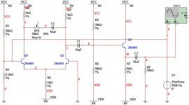
Here is my schematic for a school project. I don't know if I have the input set correctly. I will be using a modified wm-61a capsule in series with a 10k resistor , the capsule resistance is 2.2k, on a 9V battery (I have 8V on the schematic because I will be using LED's). Any help would be great. I haven't learned about differential amplifiers yet so I'm teaching myself about them so don't criticize me to harshly. Thanks
Attachments
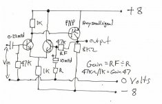
Had another look, as Peranders say's it is a bit odd. One problem is that for a 16volt supply you can only get around 4v peak/peak output before it clips. It does clip very nicely though ") . Very soft. Have a look at this. The gain is easily calculated, and it will swing nearly rail to rail. Depending on the gain you choose you may need to add a small capacitor across RF (around 47pf) to keep it stable. A similar value can also be added accross the input resistor, the 47Kohm. A.C. couple your mic capsule (the0.22 mfd cap and keep your 10k feed to the capsule).
. Very soft. Have a look at this. The gain is easily calculated, and it will swing nearly rail to rail. Depending on the gain you choose you may need to add a small capacitor across RF (around 47pf) to keep it stable. A similar value can also be added accross the input resistor, the 47Kohm. A.C. couple your mic capsule (the0.22 mfd cap and keep your 10k feed to the capsule).
Regards Karl
. Very soft. Have a look at this. The gain is easily calculated, and it will swing nearly rail to rail. Depending on the gain you choose you may need to add a small capacitor across RF (around 47pf) to keep it stable. A similar value can also be added accross the input resistor, the 47Kohm. A.C. couple your mic capsule (the0.22 mfd cap and keep your 10k feed to the capsule).Regards Karl
Attachments
Hi Andrew, your right about the imbalance of the LTP in fact you've understated it. MASSIVE, it's absolutely ENORMOUS, but the circuit does work and within certain limitations work well. I never intended it to be the ultimate in design . Also the output should really be A.C. coupled as well if it's going to feed into an audio amp. Why not make two, a discrete version and one using an I/C (OpAmp). The circuit I posted is an OpAmp (basic granted) with the bases of the two NPN transistors being the equivalent of the non inverting and inverting inputs.
Regards Karl
. Also the output should really be A.C. coupled as well if it's going to feed into an audio amp. Why not make two, a discrete version and one using an I/C (OpAmp). The circuit I posted is an OpAmp (basic granted) with the bases of the two NPN transistors being the equivalent of the non inverting and inverting inputs.Regards Karl
Yes it is basically an op-amp and I plan on using it with an RTA for my demonstration. I needed to use a differential amplifier in the project. Using Multisim, I get about a 1V output before it starts to clip with about a 50mV input, which be enough for the soundcard on my labtop. Hope this helps, and Thanks.
Hi, One further point, having looked at my scrawl earlier, as pointed out by Andrew, there is a rather large (To put it mildly) imbalance in the current distribution of the long tailed pair. Although it will work OK, if you substitute the 1K resistor in the tail with a 5K6 resistor or, better still as it's an educational project a 10K preset pot you will be able to trim the output to exactly zero volts (no signal applied). That imbalance will come down as well and the stability margin greatly improved. I think your going to have to do some practical measurements, do you have a 'scope available. In your previous post (the 140db one) , I suspect you will easily exceed 1 volt output from the preamp.
Good luck with it all, & lets hope it generates some interest.
Regards Karl
Good luck with it all, & lets hope it generates some interest.
Regards Karl
Thanks. When I designed the circuit on paper I had 5k6 resistors in there but changed it in MultiSim for a tiny bit more gain. I should have just left it. As for be able to measure 140db, I'm not going to worry about it. I'll never use it above 100db, so I'm shooting for about 110 db input before it starts to clip really bad.
Hope this is a bit clearer, I still think your going to run into problem of a lack of headroom with the original circuit you posted.
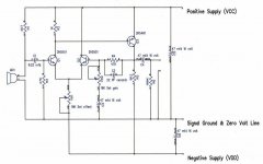
O.K. here we go, VR1 will set output to Zero D.C. volts (No signal), measure at collector of Q3.
Note the polarity of of C2. there are a few tens of millivolt here.
VR2 will adjust the gain (R4/VR2) and is usable to about 180.
Will work down to supply of +/- 3.5 volts with suitable adjustment of VR1
Output of 14v peak to peak on 16 volt supply.
Regards Karl
Attachments
Thanks Karl. I think will I make a few modifications to my circuit, I really like the your circuit. I don't plan on getting 14V pk to pk, but an output of 3V pk to pk before clipping with a fairly high input is what I'm shooting for. I'll make a few adjustments and probably build my circuit this weekend. I'll post my final schematic later. Thanks
- Status
- This old topic is closed. If you want to reopen this topic, contact a moderator using the "Report Post" button.
- Home
- Amplifiers
- Solid State
- Pre-amp school project, critique me.