Can anyone give me info on Power supply performance testing. Namley voltage regulator testing.
What test are generally usefull, how do i compare one regulator scheme VS. another perfomance wise? etc.
I have 3 regulator schematics i am interested in comparing. I have a amplifier that uses Zeners and resistors to derive +/-15vdc @ 100ma from +/-75dc rails. I want to compare the stock schem VS. using resistors to drop the voltage down to +/-30VDC then using 7815/7915 type devices or using the PASS regulator schematic.
All 3 designs should work adequitly well, but, how do i run some tests to determin which actually performs best? which would give me the cleanest power and wich would regulate the best.
Thanks
Zc
if you want to test PSRR try simply observing it on osciloscope.
if you want to test output impedance feed its output with a signal thru resistor and calculate damping.
I remember someone did a comparison in power suply forum beetween 78xx/79xx and 317/337 and the latter performed much better
if you want to test output impedance feed its output with a signal thru resistor and calculate damping.
I remember someone did a comparison in power suply forum beetween 78xx/79xx and 317/337 and the latter performed much better
Hi. Sounds like you're talking about the preamp supply on SWR!
I have found in my own experience that the 79xx is not very well matched to the 78xx, and the regulation gets worse very quickly once you get around 10v above the regulated voltage.
I'm not sure what advantage there would be to replacing the zeners. Here's one idea I don't know if you may have already done - is to monitor the supply lines on a scope while running the amp through it's rigor. That way you could check regulation, and alternatively you could check for other hash on the lines - which I would guess could be a greater issue than regulation.
Hi adrome00, depends on the test gear you have at your disposal.
Assuming the 75V rails are on a power amplifier, what I generally do to evaluate regulator performance is to run the power amplifier at the highest safe sustainable power into a dummy load and view the regulator output on a FFT analyser for a number of spot frequencies, or sweep your AP test set through a crosstalk test using ch1 to drive the amp and ch2 on the reg supplies to see residual vs hum and noise.
Assuming the 75V rails are on a power amplifier, what I generally do to evaluate regulator performance is to run the power amplifier at the highest safe sustainable power into a dummy load and view the regulator output on a FFT analyser for a number of spot frequencies, or sweep your AP test set through a crosstalk test using ch1 to drive the amp and ch2 on the reg supplies to see residual vs hum and noise.
this is exactly on a SWR amp!!!
I dont have a FFT or and Audio precision....YET! some day.
The Zeners probably do just fine. it just seems like such a brute force way to achive the end goal. There was another post where we discussed various regulator schemes. and i found the pass labs regulator schematic and that looks like it fits the bill perfectly. But what i wanted was a rock solid, but easy way to tell if i actually gained anything by using the pass labs regulator VS stock.
the SM-900 uses Two 5 watt 1,100 ohm resistors in parallel to come up with a 550 Ohm 10 watt resistor. But, that resistor stack gets pretty warm.
and they didnt use any fuses on the secondary side of the power supply, so when one channel fails as it did on mine, it Torches the board badly! because this amp was supposed to be the ultimate amp, they didnt do or use anything they felt would hinder performance or reliability. and apparantly they felt fuses would in someway hurt performance. so the only fuse you get is the 10 amp line fuse!
I would rather have a degree of protection VS the minute amount of performance degradation So i fabbed up a small board with Four 2,200 ohm resistors in parallel to reduce the heat per resistor down some and put fuses for the B+ and B- on the board. hopefully, if a channel should fail again, it wont torch the board so badly.
Back to the regulators, now then a bass amp sits idel most of the time but with slap and pop bass there are a lot of transient demands put on the power supply. I have no idea how this effects the front end at 15vdc, how quickly do the Zeners react, is there any variance in output voltage or noise. and would the Pass regulator offer better performance or lower noise.
I thought about using a small seperate transformer, but wondered if line voltage swings and noise would actually make things worse?
I dug through some old Audio Amature mags for the old Sulzer regulator schematics, but havent found them yet, and i doubt they would work well with that big if a voltage differential anyway. The Pass labs reg seems to be the way to go.
Dang i really need to get a FFT, maybe an old HP 3580A would suffice?
Zc
Sorry Zero Cool,
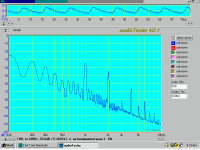
I addressed my post to the wrong person (my head fog). You can download a 90dB FFT "Audio Tester" which uses your soundcard and depends on it's quality. Below is my 250W/ch amp supply FFT, driven at 5W /8 ohms . See the harmonic artefacts due to AB.
I have built a low pass filter on the soundcard signal output to eliminate its harmonics giving 110dB noise floor (0.0003%).
Attachments
http://www.sumuller.de/audiotester/maine.htmYou can download a 90dB FFT "Audio Tester"
amplifierguru said:Sorry Zero Cool,
I addressed my post to the wrong person (my head fog). You can download a 90dB FFT "Audio Tester" which uses your soundcard and depends on it's quality. Below is my 250W/ch amp supply FFT, driven at 5W /8 ohms . See the harmonic artefacts due to AB.
I have built a low pass filter on the soundcard signal output to eliminate its harmonics giving 110dB noise floor (0.0003%).
I have seen these programs but how do you get the signal into the sound card? I would imagine you use the line in of course, but how do you condition the signal from speaker level and DC down to line level without effecting the results??
I have the SIA SIFT SMAART Pro software that is a FFT that i use for sound system setup. and that is a very powerfull FFT, and i have a FFT in soundforge and Wave lab. I did some testing of the crossover in my BMW's 10 channel amp with the SMAART software. that worked well enough to see the crossover slopes etc. but i had no way to calibrate the input levels etc to some reference. Any of these would work well enough to see noise and harmonics etc. but how do i connect a sound card to a power supply?? I am going to have to block the DC with a capacitor of course.
How about giving us a write up of the setup you use etc.
Zc
If you want to comparatively test supplies for output Z vs freq, what you do is drive a signal into the supply output through a resistor. Example: put 5V rms on a 100 ohms resistor to the supply output. That means you drive 50mA rms into the supply. You measure the residual signal at the supply. Supplose it is 1mV. You supply has an output Z of 1mV/50mA = 20mOhm.
Several caveats:
Make sure that the rms current is not higher than what the supply normally sources. Supplies cannot sink, normally. So a supply that normally delivers, say 100mA to a preamp should not be tested with more than 100mA neg peak current, so stay below 50mA rms or so.
Where do you inject the test current? Either at the point of the regulator where it's internal feedback is taken > you measure the lowest Zout; or at the point where the supply is connected to the load > you measure reality in use. Conclusion: always connect the load to the same point as the supply internal feedback point. You can easily have a 1mOhms supply connected to the load through 10mOhm of wiring. Pretty wastefull.
And oh yes, sweep the test frequency.
Jan Didden
Zero Cool said:
I have seen these programs but how do you get the signal into the sound card? I would imagine you use the line in of course, but how do you condition the signal from speaker level and DC down to line level without effecting the results??
I have the SIA SIFT SMAART Pro software that is a FFT that i use for sound system setup. and that is a very powerfull FFT, and i have a FFT in soundforge and Wave lab. I did some testing of the crossover in my BMW's 10 channel amp with the SMAART software. that worked well enough to see the crossover slopes etc. but i had no way to calibrate the input levels etc to some reference. Any of these would work well enough to see noise and harmonics etc. but how do i connect a sound card to a power supply?? I am going to have to block the DC with a capacitor of course.
How about giving us a write up of the setup you use etc.
Zc
How about AC coupling it with a cap from the power supply rail to the inputs of your sound card. Probably safest is also to reduce the voltage with a voltage divider after the cap (or before). Are those soundcard inputs protected agains overvoltage? When you switch on the supply, there will be a pretty high voltage at the input of your soundcard, dependent on how fast the power supply ramps up and what the x-over frequency of the RC filter is (due to the C for AC coupling). You can DC couple, but then you need to reduce the signal with voltage dividers and then you loose resolution as you are interested basically in the AC signal that is rising on top of the DC voltage.
By the way, I monitor my power supply rails using a scope, which is of course safer as scopes are supposed to be more robust
")
Although much more expensive than a soundcard :-(
Best regards
Gertjan
janneman said:
Where do you inject the test current? Either at the point of the regulator where it's internal feedback is taken > you measure the lowest Zout; or at the point where the supply is connected to the load > you measure reality in use. Conclusion: always connect the load to the same point as the supply internal feedback point. You can easily have a 1mOhms supply connected to the load through 10mOhm of wiring. Pretty wastefull.
And oh yes, sweep the test frequency.
Jan Didden
Seems that most power supply "stability" testing is done by inserting a transformer into the error signal chain. The transformer is driven by a sweep generator or network analyzer to derive a plot of gain and phase, the measurement points being the primary of the transformer (the secondary of the transformer usually has a 50 ohm resistor across it so that the impedance matches that of the analyzer) National Semiconductor, Lecroy, Tektronix and others have good application notes on the procedure. Of course, you need a really good transformer.
You could also use a high speed opamp -- Micrel had a small article in EDN about a year ago which I posted on DIYAUDIO. The opamp takes the place of the transformer with some caveats. I think Galinski wrote the article so search unde his name.
Of course, I like to bang my power supplies by rapidly changing the load and seeing what happens. You can do this with a FET switch .
Noise testing -- you don't need an audio-precision tester -- Texas Instruments and Linear Technology will show you how to do it -- if you look at the TI product folder for the TL431 adjustable reference they have a schematic for a noise testing circuit with the correct filters. Walt Jung also described a circuit in the 1995 series of articles in Audio Amateur -- his was based upon the now discontinued SSM2017 from ADI -- the SSM2019 can be used instead and has very low THD.
When you are measuring in the microvolts you have to be very careful of your "probing" -- in fact, rather than probing it seems optimal to solder 50 ohm cable to the points of interest. Best if the DUT is placed in a shielded container (we don't all have Faraday shielded rooms) -- Jim Williams from Linear Tech uses a Danish Butter Cookie tin !
Here's a link to Galinski's design note on using an opamp for Bode analysis:
http://www.edn.com/article/CA450603.html?text=galinski
http://www.edn.com/article/CA450603.html?text=galinski
jackinnj said:
Seems that most power supply "stability" testing is done by inserting a transformer into the error signal chain. The transformer is driven by a sweep generator or network analyzer to derive a plot of gain and phase, the measurement points being the primary of the transformer (the secondary of the transformer usually has a 50 ohm resistor across it so that the impedance matches that of the analyzer) National Semiconductor, Lecroy, Tektronix and others have good application notes on the procedure. Of course, you need a really good transformer.
You could also use a high speed opamp -- Micrel had a small article in EDN about a year ago which I posted on DIYAUDIO. The opamp takes the place of the transformer with some caveats. I think Galinski wrote the article so search unde his name.
Of course, I like to bang my power supplies by rapidly changing the load and seeing what happens. You can do this with a FET switch .
Noise testing -- you don't need an audio-precision tester -- Texas Instruments and Linear Technology will show you how to do it -- if you look at the TI product folder for the TL431 adjustable reference they have a schematic for a noise testing circuit with the correct filters. Walt Jung also described a circuit in the 1995 series of articles in Audio Amateur -- his was based upon the now discontinued SSM2017 from ADI -- the SSM2019 can be used instead and has very low THD.
When you are measuring in the microvolts you have to be very careful of your "probing" -- in fact, rather than probing it seems optimal to solder 50 ohm cable to the points of interest. Best if the DUT is placed in a shielded container (we don't all have Faraday shielded rooms) -- Jim Williams from Linear Tech uses a Danish Butter Cookie tin !
I just "bang" my power supplies by suddenly changing the resistance of the dummy load by switching manually a mains switch that connects additional dummy loads resistors to the load. This works very well.
You can see what I did in the class D section in the K6 SMPS thread.
that's not going to tell you a whole lot about a power supply which may be prone to oscillation -- something which should be well considered in switching amplifiers with a lot of potential for clock noise. but I acknowledge that I use the "larger hammer" method myself.ghemink said:
I just "bang" my power supplies by suddenly changing the resistance of the dummy load by switching manually a mains switch that connects additional dummy loads resistors to the load. This works very well.
You can see what I did in the class D section in the K6 SMPS thread.
- Status
- This old topic is closed. If you want to reopen this topic, contact a moderator using the "Report Post" button.
- Home
- Amplifiers
- Power Supplies
- Power supply performance testing? How To