Portable speaker with HiWave BMRs - lots of photos
Preamble
Last summer I messed around with various portable speakers, starting from a (gutted) Bose iPod dock, then moving on to various other speakers, including (biamped) a cheap Sony 5.1 system.
Of course, these set-ups varied quite a lot in portability, size, and volume.
I used this amplifier board:

It'll run on 5-15v DC, and (at higher supply voltages) put out 10w/ch into 8ohm. Fully protected against any output fault, too.
I used this with 7.2v remote control car batteries, as I had them lying around. A couple of them would keep it running for an afternoon.
It'd usually sound reasonable, certainly better than any off-the-shelf portable speaker.
__________________________________________________________________________________________________
I've decided to do something a bit better this time around. This is going to be my final small-and-portable speaker project. Probably.
In the interests of decent dispersion, I've bought myself 4 of the following:
www.hi-wave.com/downloads/datasheets/DS-HIBM36S12-4A.pdf
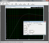
A few different BMRs were available from RS, but these (and the 4" round one) were the only ones to offer half-decent frequency response. The drivers have a healthy Xmax and reasonable sensitivity, but (according to WinISD) won't go below 100Hz.
The Bose system I played with earlier had similar characteristics, but avoided sounding anaemic by making use of a couple of dBs peak before rolloff. I plan to do something similar here (WinISD plots attached). The Boominator (over on the Class D forum) appears to use the same idea: forget about going low, just make sure what it can do is at a decent level.
I'll be using the same amplifier board as before, and will be incorporating an 8xAA battery holder into the system. This will be run from rechargable batteries, or normal AAs if anyone has them to spare. I find this to be a good solution for smaller systems like this. The problem I had previously was that, once the batteries had emptied, it was a 4 hour wait until it can be used again. I might incorporate a seperate DC input so I can use other power sources (inc. wall-wart).
The drivers will be wired 2 per side, wired in series. This will give an 8ohm load, so the amplifier will be happy. Before now we've had it go into thermal protection, but that's another story.
Here's a question for the audience.
With two drivers per channel, I could go for the Boominator-style approach and use the drivers as a bipole configuration, so BSC is conveniently taken care of.
Alternatively, I could have all 4 drivers firing forward.
Thoughts on the pros/cons of each?
The construction will be 9mm MDF all round, as that's what I have here*. I'm still working on some details: for example, I'm still not sure where would be best to mount the battery compartment. Opinions and ideas would be welcomed here.
*it also works out nicely for driver mounting: 6mm thick would mean the driver pokes forward slightly, risking damage. The 9mm will allow some protection of the drivers - grilles may be added depending on how much of a risk I assess this to be.
I saw this thread a few years back, and have decided to try to copy this finish, using red paint instead of blue. The instructions there are detailed enough for me to make a fair stab at copying this, so I'm optimistic that, if nothing else, this'll look pretty awesome.
I have some photos of the various bits I've bought, but they're currently 80 miles away, so I'll upload them next week when I'm back.
I'll update this as things develop. If the weather's nice, I'll be trying my hand with the spray cans.
Sorry about the long post, congratulations if you've made it this far.
Chris
NOTE - click on the images to get them to their original aspect ratios. Embedding them does weird things to the preview.
Preamble
Last summer I messed around with various portable speakers, starting from a (gutted) Bose iPod dock, then moving on to various other speakers, including (biamped) a cheap Sony 5.1 system.
Of course, these set-ups varied quite a lot in portability, size, and volume.
I used this amplifier board:
It'll run on 5-15v DC, and (at higher supply voltages) put out 10w/ch into 8ohm. Fully protected against any output fault, too.
I used this with 7.2v remote control car batteries, as I had them lying around. A couple of them would keep it running for an afternoon.
It'd usually sound reasonable, certainly better than any off-the-shelf portable speaker.
__________________________________________________________________________________________________
I've decided to do something a bit better this time around. This is going to be my final small-and-portable speaker project. Probably.
In the interests of decent dispersion, I've bought myself 4 of the following:
www.hi-wave.com/downloads/datasheets/DS-HIBM36S12-4A.pdf
A few different BMRs were available from RS, but these (and the 4" round one) were the only ones to offer half-decent frequency response. The drivers have a healthy Xmax and reasonable sensitivity, but (according to WinISD) won't go below 100Hz.
The Bose system I played with earlier had similar characteristics, but avoided sounding anaemic by making use of a couple of dBs peak before rolloff. I plan to do something similar here (WinISD plots attached). The Boominator (over on the Class D forum) appears to use the same idea: forget about going low, just make sure what it can do is at a decent level.
I'll be using the same amplifier board as before, and will be incorporating an 8xAA battery holder into the system. This will be run from rechargable batteries, or normal AAs if anyone has them to spare. I find this to be a good solution for smaller systems like this. The problem I had previously was that, once the batteries had emptied, it was a 4 hour wait until it can be used again. I might incorporate a seperate DC input so I can use other power sources (inc. wall-wart).
The drivers will be wired 2 per side, wired in series. This will give an 8ohm load, so the amplifier will be happy. Before now we've had it go into thermal protection, but that's another story.
Here's a question for the audience.
With two drivers per channel, I could go for the Boominator-style approach and use the drivers as a bipole configuration, so BSC is conveniently taken care of.
Alternatively, I could have all 4 drivers firing forward.
Thoughts on the pros/cons of each?
The construction will be 9mm MDF all round, as that's what I have here*. I'm still working on some details: for example, I'm still not sure where would be best to mount the battery compartment. Opinions and ideas would be welcomed here.
*it also works out nicely for driver mounting: 6mm thick would mean the driver pokes forward slightly, risking damage. The 9mm will allow some protection of the drivers - grilles may be added depending on how much of a risk I assess this to be.
I saw this thread a few years back, and have decided to try to copy this finish, using red paint instead of blue. The instructions there are detailed enough for me to make a fair stab at copying this, so I'm optimistic that, if nothing else, this'll look pretty awesome.
I have some photos of the various bits I've bought, but they're currently 80 miles away, so I'll upload them next week when I'm back.
I'll update this as things develop. If the weather's nice, I'll be trying my hand with the spray cans.
Sorry about the long post, congratulations if you've made it this far.
Chris
NOTE - click on the images to get them to their original aspect ratios. Embedding them does weird things to the preview.
Attachments
Last edited:
An update...
First off, I grabbed a spare MDF cabinet I had lying around, and had a go with the spray cans.
Black-coloured primer was sprayed on, with a few minutes between layers. I think I did 3 or 4 layers overall, then left it to dry off overnight.
Next, I put a couple of layers of red on, same method as the first layer.
Took some 400 grit sand paper and, after quite a bit of sanding, got this:
Apologies about the big photos - I uploaded them to another site then embedded them here.
I learnt a few things:
1 - be gentle with the sandpaper (went too far in places)
2 - round over the edges - that way, the bare MDF won't show.
3 - keep the sandpaper clean: there are some scrape marks where the paint had accumulated and compacted on the sandpaper, resulting in a hard lump that left the marks. You'll probably be able to spot this on the photos
Having gained that experience, I decided that it was time to cut up some wood. This meant settling on a design.
I decided to go with the Boominator bipole layout, in the interests of compactness. With the battery compartment, fitting 4x BMRs on one baffle would've proved difficult. The bipole arrangement would also sort out BSC, meaning it won't be found lacking in LF if elevated (a problem with many store-bought iPod docks).
This morning I cut up the necessary wood, using the 9mm MDF.
Here's the obligatory photos.
and the dry-fit (where the 2nd photo was taken - I haven't used a hand-saw for years)
I need to cut the bottom piece down so that the 8x AA battery compartment can sit underneath. You can see where its meant to go.
When I get back to Sheffield (the train's tomorrow), I'll upload the photos of the drivers, and start sanding then gluing.
Chris
First off, I grabbed a spare MDF cabinet I had lying around, and had a go with the spray cans.
Black-coloured primer was sprayed on, with a few minutes between layers. I think I did 3 or 4 layers overall, then left it to dry off overnight.
Next, I put a couple of layers of red on, same method as the first layer.
Took some 400 grit sand paper and, after quite a bit of sanding, got this:
An externally hosted image should be here but it was not working when we last tested it.
An externally hosted image should be here but it was not working when we last tested it.
An externally hosted image should be here but it was not working when we last tested it.
An externally hosted image should be here but it was not working when we last tested it.
Apologies about the big photos - I uploaded them to another site then embedded them here.
I learnt a few things:
1 - be gentle with the sandpaper (went too far in places)
2 - round over the edges - that way, the bare MDF won't show.
3 - keep the sandpaper clean: there are some scrape marks where the paint had accumulated and compacted on the sandpaper, resulting in a hard lump that left the marks. You'll probably be able to spot this on the photos
Having gained that experience, I decided that it was time to cut up some wood. This meant settling on a design.
I decided to go with the Boominator bipole layout, in the interests of compactness. With the battery compartment, fitting 4x BMRs on one baffle would've proved difficult. The bipole arrangement would also sort out BSC, meaning it won't be found lacking in LF if elevated (a problem with many store-bought iPod docks).
This morning I cut up the necessary wood, using the 9mm MDF.
Here's the obligatory photos.
An externally hosted image should be here but it was not working when we last tested it.
An externally hosted image should be here but it was not working when we last tested it.
and the dry-fit (where the 2nd photo was taken - I haven't used a hand-saw for years)
An externally hosted image should be here but it was not working when we last tested it.
I need to cut the bottom piece down so that the 8x AA battery compartment can sit underneath. You can see where its meant to go.
When I get back to Sheffield (the train's tomorrow), I'll upload the photos of the drivers, and start sanding then gluing.
Chris
")
Back in Sheffield, here's some photos.
Hi Jules, thanks for the interest.
This evening I've had the coping saw out, attempting to cut the holes for the speaker.
The first hole went quite well, and things went downhill from there. I've also marked out the screw-holes for the battery holder, but that's fairly trivial.
Here's some BMRs.
Here's a close-up.
Here's the battery holder, that's going to be mounted underneath.
Marking out the baffles...
... the markings made sense at the time, I swear!
Next up, make holes to get the coping saw in there. I'm in student accomodation, so my old (1979) guitar amp serves as a workbench.
Holes made, small pile of dust on carpet. The Stanley Fatmax saw is a good 'un.
First driver cutout done. MDF dust pile has grown a little.
All cutouts done.
There's some sanding ahead to get things to fit together nicely, but then its glue and finishing.
I'm still waiting on an amplifier board arriving - the one I used previously is doing service in the girlfriend's stereo, and she won't give it back.
I'm going to glue a few basic things together, but avoid going too far so that I can easily install connectors etc.
Chris
Hi Jules, thanks for the interest.
This evening I've had the coping saw out, attempting to cut the holes for the speaker.
The first hole went quite well, and things went downhill from there. I've also marked out the screw-holes for the battery holder, but that's fairly trivial.
Here's some BMRs.
An externally hosted image should be here but it was not working when we last tested it.
Here's a close-up.
An externally hosted image should be here but it was not working when we last tested it.
Here's the battery holder, that's going to be mounted underneath.
An externally hosted image should be here but it was not working when we last tested it.
Marking out the baffles...
An externally hosted image should be here but it was not working when we last tested it.
... the markings made sense at the time, I swear!
Next up, make holes to get the coping saw in there. I'm in student accomodation, so my old (1979) guitar amp serves as a workbench.
An externally hosted image should be here but it was not working when we last tested it.
Holes made, small pile of dust on carpet. The Stanley Fatmax saw is a good 'un.
An externally hosted image should be here but it was not working when we last tested it.
First driver cutout done. MDF dust pile has grown a little.
An externally hosted image should be here but it was not working when we last tested it.
All cutouts done.
An externally hosted image should be here but it was not working when we last tested it.
There's some sanding ahead to get things to fit together nicely, but then its glue and finishing.
I'm still waiting on an amplifier board arriving - the one I used previously is doing service in the girlfriend's stereo, and she won't give it back.
I'm going to glue a few basic things together, but avoid going too far so that I can easily install connectors etc.
Chris
Last edited:
Short update
As mentioned previously, the first driver cut-out went quite well, but the rest were fairly terrible.
Fortunately, I have some files. More dust has been made.
I used one of the drivers to test-fit and see where needs filing down, but here's a family shot of them all.
Here's the backs.
No mounting screws yet. I think I'll have to go for M3 nuts and bolts, or some really really short wood screws. Hmmmm...
That's all for tonight, as its just past midnight.
Chris
As mentioned previously, the first driver cut-out went quite well, but the rest were fairly terrible.
Fortunately, I have some files. More dust has been made.
An externally hosted image should be here but it was not working when we last tested it.
I used one of the drivers to test-fit and see where needs filing down, but here's a family shot of them all.
An externally hosted image should be here but it was not working when we last tested it.
Here's the backs.
No mounting screws yet. I think I'll have to go for M3 nuts and bolts, or some really really short wood screws. Hmmmm...
An externally hosted image should be here but it was not working when we last tested it.
That's all for tonight, as its just past midnight.
Chris
Another update
Haven't updated this for a few days. Not much has happened until this morning.
Earlier this week, I glued a few things up, to get here:
So, the next task was to add a bass reflex port.
I'm using 40mm (ext diameter) pipe. The internal length comes out around 70mm, giving me the ~150Hz tuning. You can see the pipe in one of the photos from the 25th of March.
Without any 40mm drill bits (or a drill that would handle it), I tried my hand at chain drilling.
The idea is to make a lot of little holes in a line, then join them all up.
I marked out a 40mm circle, and then a 38mm circle, concentric with the first. This meant I had somewhere to aim with a 2mm drill bit.
Join all the holes up...
I knocked it out with a hammer because the knife didn't quite go deep enough.
As you can imagine, the edge of the hole was far from smooth.
Got the trusty half-round file and made it so.
After a while, I (via application of not-inconsiderable force) managed to push the pipe into the hole.
The hole wasn't perfectly round, but the pipe conformed quite nicely.
Not to waste a happy accident, I chamfered the edge where the wood and pipe meet, to make a smooth join.
I applied some superglue to hold the pipe still, then ran a thick bead of PVA around to ensure the join was airtight.
I have also glued the penultimate piece in place:
A note on gluing.
I'm not sure who it was, but someone on this forum mentioned (a long time ago) that applying superglue as well as PVA was the way to go.
This person was absolutely right.
Previously (as in, before this project) I had used PVA and a lot of clamps to get things in place. So long as you get it right within a few seconds, the superglue sets and holds the join exactly where you want it.
I've also ordered a snazzy on/off button:
It has occurred to me that, in order to finish this project off, I need to spray paint the outside.
However, the only way of mounting the drivers is from the inside.
Ideally, everything would be glued together, so that I can spray and sand in one go. However, if I wanted to go that I'd have to cover everything over to stop the drivers, button, volume control being painted.
That would be difficult to implement.
So, I've decided to get everything sanded down so that it all fits together perfectly, with no edges sticking out, and then paint the front plus sides and top together, and the rear baffle seperately.
Once the paint is dry and everything is mounted where it ought to be, I can finally glue the last piece in place.
I'll try to match the finish of the top/sides to the rear baffle, but this is a semi-experimental project, so I won't mind all that much if things don't line up exactly.
Chris
PS - the button arrived today, and it lights up quite brightly off the 9.6v from the batteries. Rather pleased about that. I'll make a hole for that now - chain drilling as before.
Haven't updated this for a few days. Not much has happened until this morning.
Earlier this week, I glued a few things up, to get here:
An externally hosted image should be here but it was not working when we last tested it.
So, the next task was to add a bass reflex port.
I'm using 40mm (ext diameter) pipe. The internal length comes out around 70mm, giving me the ~150Hz tuning. You can see the pipe in one of the photos from the 25th of March.
Without any 40mm drill bits (or a drill that would handle it), I tried my hand at chain drilling.
The idea is to make a lot of little holes in a line, then join them all up.
I marked out a 40mm circle, and then a 38mm circle, concentric with the first. This meant I had somewhere to aim with a 2mm drill bit.
An externally hosted image should be here but it was not working when we last tested it.
Join all the holes up...
An externally hosted image should be here but it was not working when we last tested it.
I knocked it out with a hammer because the knife didn't quite go deep enough.
As you can imagine, the edge of the hole was far from smooth.
Got the trusty half-round file and made it so.
After a while, I (via application of not-inconsiderable force) managed to push the pipe into the hole.
The hole wasn't perfectly round, but the pipe conformed quite nicely.
Not to waste a happy accident, I chamfered the edge where the wood and pipe meet, to make a smooth join.
I applied some superglue to hold the pipe still, then ran a thick bead of PVA around to ensure the join was airtight.
I have also glued the penultimate piece in place:
An externally hosted image should be here but it was not working when we last tested it.
A note on gluing.
I'm not sure who it was, but someone on this forum mentioned (a long time ago) that applying superglue as well as PVA was the way to go.
This person was absolutely right.
Previously (as in, before this project) I had used PVA and a lot of clamps to get things in place. So long as you get it right within a few seconds, the superglue sets and holds the join exactly where you want it.
I've also ordered a snazzy on/off button:
An externally hosted image should be here but it was not working when we last tested it.
It has occurred to me that, in order to finish this project off, I need to spray paint the outside.
However, the only way of mounting the drivers is from the inside.
Ideally, everything would be glued together, so that I can spray and sand in one go. However, if I wanted to go that I'd have to cover everything over to stop the drivers, button, volume control being painted.
That would be difficult to implement.
So, I've decided to get everything sanded down so that it all fits together perfectly, with no edges sticking out, and then paint the front plus sides and top together, and the rear baffle seperately.
Once the paint is dry and everything is mounted where it ought to be, I can finally glue the last piece in place.
I'll try to match the finish of the top/sides to the rear baffle, but this is a semi-experimental project, so I won't mind all that much if things don't line up exactly.
Chris
PS - the button arrived today, and it lights up quite brightly off the 9.6v from the batteries. Rather pleased about that. I'll make a hole for that now - chain drilling as before.
Another quick update
The snazzy button arrived today, so I got to work.
First, a 16mm hole is marked and chain-drilled, giving this:
Clearly, however, the half-round file isn't gonna fit in there.
I don't have a round file, so had to figure out something else.
Got some gaffer tape, coarse sandpaper, and an 8mm drill bit.
Spin that in the drill, and you can remove material quite quickly.
A power drill would've been nice for that bit, but nevermind.
... and eventually, the button fits.
Chris
The snazzy button arrived today, so I got to work.
First, a 16mm hole is marked and chain-drilled, giving this:
An externally hosted image should be here but it was not working when we last tested it.
Clearly, however, the half-round file isn't gonna fit in there.
I don't have a round file, so had to figure out something else.
Got some gaffer tape, coarse sandpaper, and an 8mm drill bit.
An externally hosted image should be here but it was not working when we last tested it.
Spin that in the drill, and you can remove material quite quickly.
A power drill would've been nice for that bit, but nevermind.
... and eventually, the button fits.
An externally hosted image should be here but it was not working when we last tested it.
Chris
The project is indeed finished, though I haven't had much time recently to post about it.
Sounds rather good, especially given the size.
I'd say the sound is a little sibilant at times, and there's not much below 120Hz. The low end works okay for most stuff, just lacks the oomph of bigger speakers. That would be me being a little critical - I recently took it on a weekend away, where I got a few compliments on the sound.
IMO, something bigger would be useful to have, so I'm thinking of taking the 8" dual-coil woofers I have and pairing them up with some KEF egg coaxials to make a suitcase-sized boombox.
I'm wondering whether it'd be best to go for 2x8"ers, or 1x12"er, but I'll probably take the cheap option and use the 8" drivers I already have.
Lessons learnt:
1 - always cut down the correct side of the line
2 - be gentle with the file (the driver cutouts are in no way neat or tidy)
3 - decide what you want to do with the finish before you sand down the outer layer
4 - make sure you can get full power output using devices with a relatively quiet headphone output.
5 - ensure the volume knob can be sunk into the wood a decent amount - it currently sticks out a long way, making transport awkward.
I'll post pictures later in the week, but I'm fairly happy with how its turned out overall.
Chris
How is the sound of the BMR (off axis, etc?) I'm looking at making a L/C/R sound stand with the 3.5 inch driver (if they ever get them). It's either the BMR's or B3S and there is just no data on Hiwave's products out there.
Interesting project Chris. good job.
With mine (remember - these are the 65mm square ones, so this might not translate directly to yours), perfectly on-axis is quite harsh. Anywhere off-axis sounds very similar, so I'd expect these to work well for HT with several audience members.
Note that I'm using a bipole arrangement, so BSC will be needed if you only run one per channel.
When pushed loud, mine also suffer the same cone break-up sound of so many other FR speakers - harsh upper mids. I'm currently sticking roughly 20w peaks through 4 of them, and it works quite nicely - fills a room with ~15 people having conversations, but the cone break-up threshold isn't passed, so it still sounds nice.
You may or may not find the cone break-up/distortion a problem, depending on how loud you like movies. You're looking at relatively small drivers, so my advice would be expect decent sound, but its not gonna rock your socks off.
Chris
- Status
- This old topic is closed. If you want to reopen this topic, contact a moderator using the "Report Post" button.
- Home
- Loudspeakers
- Full Range
- Portable speaker with HiWave BMRs