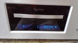
My Esoteric CD player suddenly stopped working while it was playing a CD. The CD tray does not open/close and no mechanical movement at all when pressing open/close.
I opened it up and measured voltage supply to pin 8 (Vcc) on motor driver chip BA5969FP, it reads 0.
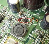
So I traced the power rail all the way to the power supply board, and I found the input voltage to the regulator IC (00DD0W) is also 0.
I then found the diode inside the red circle in picture has shorted. It looks like a protection diode connected across the input of the regulator.
Now, to replace it, what type of diode this is? My first guess is 50V zener?
I opened it up and measured voltage supply to pin 8 (Vcc) on motor driver chip BA5969FP, it reads 0.
So I traced the power rail all the way to the power supply board, and I found the input voltage to the regulator IC (00DD0W) is also 0.
I then found the diode inside the red circle in picture has shorted. It looks like a protection diode connected across the input of the regulator.
Now, to replace it, what type of diode this is? My first guess is 50V zener?
Attachments
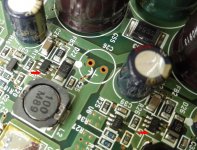
I found the 10R (R17) resistor value become 500R so I replaced it. Power did come back, the output voltage was just about 7V. Tray open/close no problem, but won't read, just kept spinning. After a minute, 7V dropped again. Now the resistor 33R (R20) looks a bit burned and measures 300R. I think the 6 pin device is very obviously shorted when compare to the other one device next to it. What's the 6 pin device? It has " TZ1" laser printing on it.
I think that 6pin device could be the cause of the problem, look the PCB , the nearby area looks yellowish. The photo was taken before.
I think that 6pin device could be the cause of the problem, look the PCB , the nearby area looks yellowish. The photo was taken before.
Attachments
Last edited:
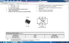
50 means MM5Z2V4, a Zener diode!
Thanks, I did a bit search , according to s-manual website the smd code 50 is MM5Z2V4:
http://www.s-manuals.com/smd/50
it's a 2.4V Zener diode. But I have a question, in the picture I attached, I measured the voltage across the same type diode next to it (D26), it's 5.5V , how can it be working safe and fine?
Q6 could be a dual transistor, either BJT small signal, or FET small signal.
Andrew,
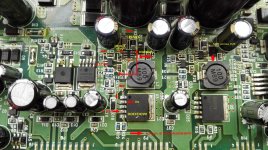
Now I have a photo taken with Q6 removed. Would it be possible to figure it out by the look of traces connected to Q6?
Also, regulator U3 00DD0W should output 8.2V according to the formula in its pdf. It's set by 2 resistors connected to pin 5 and ground, Vo= 1.27X (1+ R19/R24), here R19=13K and R24=2.4K
Attachments
Last edited:
Is this mystery diode placed across the regulated rail ? and are those regulators 'linear' types or switching ?
It certainly looks to be across the rail from the photo.
If it is across the rail and if it is a linear regulator then it could well be a fast acting 'zener type' of device used as overvolts protection. These are common in lots of gear and they can fail for no obvious reason.
If its a switching regulator then and the diode is across the supply then it is most like a high speed soft recovery flyback type of device and a vital part of the circuit. I ask about SMPS because of the two coils next to the regs.
Could the other device be used to put the regs (and so the unit) into standby ? or could it be an optocoupler used for feedback ?
Is this mystery diode placed across the regulated rail ? and are those regulators 'linear' types or switching ?
It certainly looks to be across the rail from the photo.
If it is across the rail and if it is a linear regulator then it could well be a fast acting 'zener type' of device used as overvolts protection. These are common in lots of gear and they can fail for no obvious reason.
If its a switching regulator then and the diode is across the supply then it is most like a high speed soft recovery flyback type of device and a vital part of the circuit. I ask about SMPS because of the two coils next to the regs.
Could the other device be used to put the regs (and so the unit) into standby ? or could it be an optocoupler used for feedback ?
Thanks for analysis. My first guess the diode is a Zener too. I think it failed becuse Q6 failed. The whole power supply board has all linear regulators. U3's input voltage come from Q6, which gets fed from a traditional rectifier/filter. Two coil are just CLC filter after Q6 and Q7. The right part produces 5V and it is all most the same as the left part. The right part pruduces 8.2V through U3 to motor driver chip on a separate board, this voltage is not present right now causing CD player no mechnical movement at all.
If they are linear regs then the diode is either a protection device designed to fail short in the event of an overvoltage or possibly just some form of back emf protection (a fast diode).
The six legged smd could be anything but there are transient suppressors in that package style.
Without a circuit or having the unit in front of me its all guesswork though.
The six legged smd could be anything but there are transient suppressors in that package style.
Without a circuit or having the unit in front of me its all guesswork though.
Attachments
If they are linear regs then the diode is either a protection device designed to fail short in the event of an overvoltage or possibly just some form of back emf protection (a fast diode).
The six legged smd could be anything but there are transient suppressors in that package style.
Without a circuit or having the unit in front of me its all guesswork though.
Since it's marked Q6 on PCB, Usually Q=BJT/JFET, R= resistor, U=IC/Regs, ...... Also, on the PCB it looks equivalent to a 3 legs device.
I found a SOT26 P channel device and I think it has the same pin configuration. See the photo attached.
Does it make sense? If yes, what's this P channel Mosfet is here for?
Attachments
Last edited:
If it were something like that then it would be used as a solid state switch (in place of a relay) to switch a rail. If it were P channel then the source would connect to the more positive point in the circuit.
If you really believe its a device like this and the 'print fits' then you could try shorting D to S and seeing if the missing rail comes up.
That's at your own risk of course... you need to be very sure that it is this type of device.
If you really believe its a device like this and the 'print fits' then you could try shorting D to S and seeing if the missing rail comes up.
That's at your own risk of course... you need to be very sure that it is this type of device.
If it were something like that then it would be used as a solid state switch (in place of a relay) to switch a rail. If it were P channel then the source would connect to the more positive point in the circuit.
If you really believe its a device like this and the 'print fits' then you could try shorting D to S and seeing if the missing rail comes up.
That's at your own risk of course... you need to be very sure that it is this type of device.
Thanks for your advice.
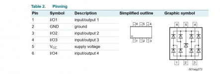
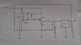
I have more findings during the weekend. The circuit actually contains a DC-DC converter before the linear reg. 00DD0W. It involves U4, Q6 (P channel Mosfet) , L2, D22. D22 is actually a Schottky diode. I found XC9221 from Torex matches the print on PCB.
Now I have a schematic about this, I will test this when all the parts delivered.
Attachments
Last edited:
Excellent. That confirms my earlier suspicion of wondering if there was an SMPS element to all this.

After replacing Q6, R20, R17, R16 and D22, my Esoteric CD player is now back to life again !
Thanks Mooly and everyone.
Attachments
")
- Status
- This old topic is closed. If you want to reopen this topic, contact a moderator using the "Report Post" button.
- Home
- Amplifiers
- Power Supplies
- please help to identify a diode (power supply related)