I had trouble with 1k5 ct DIY custom transformer. burned.
I want to plan to use 2 pieces Power transformer of Hashimoto / PT250.
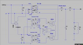
using 866A mercury vapour rectifier and delay relay tube Amperite 115N030 for preheating.
suggestions for it
thank you.
to the scheme:
I want to plan to use 2 pieces Power transformer of Hashimoto / PT250.
using 866A mercury vapour rectifier and delay relay tube Amperite 115N030 for preheating.
suggestions for it
thank you.
to the scheme:
Attachments

Mercury vapor rectifiers are much happier with choke input loading; peak currents above rating shortens their life considerably.
Amperite delay relays will not survive switching much current. You'll need an intermediate relay between the Amperite and the plate transformer(s). You might also consider designing a latch that turns off the Amperite's heater after use. This can give you some robustness during brief power outages, otherwise a source of potential drama. Drama at these voltages is not good.
All good fortune,
Chris
Mercury vapor rectifiers are much happier with choke input loading; peak currents above rating shortens their life considerably.
Amperite delay relays will not survive switching much current. You'll need an intermediate relay between the Amperite and the plate transformer(s). You might also consider designing a latch that turns off the Amperite's heater after use. This can give you some robustness during brief power outages, otherwise a source of potential drama. Drama at these voltages is not good.
All good fortune,
Chris
Hi Chris,
Thank you for your response,
to choke the input I have not had a while like that... temporary.
I do not understand the "intermediate relay between the Amperite and the plate transformer (s)" please, you explain to me .. because actually I am still a beginner to this.
I gave amperite delay in Primary because I doubted in limitations put on the secondary. Is this correct?
actual load current of no more than 200 ma, is this enough to survive?
best Regards
ed
Yes, Chris is right about the choke input with mercury vapor rectifiers. Do NOT use the delay tube contacts to connect power to the HV transformer. They are not strong enough for that much current. Use it to power a relay with 10 amp contacts for that and choose one with extra contacts to bypass the thermal timer as it kicks in. This will preserve the thermal delay. And use a 60 second delay instead of only 30. The tubes will thank you. This is how the big boys always did it. (Kepco, Lambda and others)
Hi Chris,
Thank you for your response,
to choke the input I have not had a while like that... temporary.
I do not understand the "intermediate relay between the Amperite and the plate transformer (s)" please, you explain to me .. because actually I am still a beginner to this.
I gave amperite delay in Primary because I doubted in limitations put on the secondary. Is this correct?
actual load current of no more than 200 ma, is this enough to survive?
best Regards
ed
A beginner should not work with 1000 volts !
Amperite delay relays are bi-metal type and close *very* slowly. During the last part of closing they arc across and are damaged by the arcing.
If they're used to operate a relay that both turns on the plate transformer (and, ideally, a filament transformer for the damper diode(s) used to bring HV up slowly) and turns off the Amperite's heater, they'll be fine.
This is quite a demanding project for a beginner, and I wish you the best.
All good fortune,
Chris
Drama at these voltages is not good.
Drama at those energy levels result in explosions. I've had parts blow apart violently at much lower voltages than 1 kV.
A beginner should not work with 1000 volts !
I agree.
Tom
Amperite delay relays are bi-metal type and close *very* slowly. During the last part of closing they arc across and are damaged by the arcing.
If they're used to operate a relay that both turns on the plate transformer (and, ideally, a filament transformer for the damper diode(s) used to bring HV up slowly) and turns off the Amperite's heater, they'll be fine.
This is quite a demanding project for a beginner, and I wish you the best.
All good fortune,
Chris
thanks to friends who give a warning to me ...
I understand and fear to work with high voltage ..
But there are curious to try it out ... for that I am trying to get some expert advice to avoid the fatality and learn for it.
This has become my first project for 1K ... feel afraid
initial experiment .. i get burned PT.
so I did not dare to PT costume.
there is always a fear. but I try to be careful
Chris, thank you for you explain..
I just understand "whether Amperite can always stand by for a long time to load?" I recently met idea to plan using the tube relay delay.
it looks like it is becoming a problem.
before I plan to use SPDT relay coils.
thank you
regards
ed
Last edited:
Put the bleeder resistor, R1 after the chokes. It reduces the amount of inductance needed with choke input. Capacitor input like you have will be noisy. Need to get rid of the first cap or face alot of switching noise.
thank you for you advise..
i will replace The Bleeder R1 to C2
thank you for you advise..
i will replace The Bleeder R1 to C2
sorry .to C6
My friend suggested adding 6ax4 damper tube, connection CT to the anode and cathode to gnd to provide shock absorbers. slow start of HV at 866A.
what do you think of this?
Anyone else note that this circuit puts a half wave load on two power transformers that were not designed for it?
Many transformers will buzz, overheat, or flat out saturate when connected like this. The peak voltage from the hot end of the secondary to ground is about 1400 volts. Probably a bit more than was intended, but maybe OK depending on the insulation quality of the transformer. I have not seen Hashimoto transformers, or know if they can survive in a half wave design.
If I had to use these transformers to make 1KV, I would build two conventional 500 volt supplies, and wire them in series. Peak transformer voltages would be similar, but both would operate as full wave supplies. 4 rectifiers would be needed, but the PIV requirements are less.
I needed a low buck 1KV supply, so I used a 480 to 120 (or 240) volt industrial control transformer wired backwards feeding a full wave voltage doubler made with a pair of 5AR4's. It produces 1050 volts when feeding two 845 tubes at 100 mA each. Cost, less that $100 for everything using an Ebay sourced transformer. The original Sovtek 5AR4's are still in the amp.
If none of this makes sense, get some experienced help before playing with 1KV, next time it might be something more important than a transformer that burns!
I think most of us stop reading after seeing 1kV, be afraid, very afraid...Anyone else note that this circuit puts a half wave load on two power transformers that were not designed for it?
")
sorry .to C6
My friend suggested adding 6ax4 damper tube, connection CT to the anode and cathode to gnd to provide shock absorbers. slow start of HV at 866A.
what do you think of this?
The damper diode actually connects the other way around, cathode to CT, anode to signal ground. All of the power supply capacitors need to get charged up at turn-on, and chokes in series are little more than their resistance at charging rates, causing high peak currents for a (short) while. Slow turn-on by the damper diode helps keep this managable.
Just another of the pitfalls of mercury vapor rectifiers. The good news is you'll learn a lot about the old ways of constructing widow-makers, and learning is its own reward.
All good fortune,
Chris
ps: Type 6AX4 will be strained at 200mA. You might want to use two in parallel, or a bigger diode.
suwaned,
I am requesting that you seek to build a simpler and 'safer' power supply. You have already burned a transformer and I am glad that is all that went wrong. Take for instance, Decware's zkit1. This is a nice sounding little amp to cut your teeth on. This power supply still is easily able to kill you but it is easier to work with than anything above 600V (this is a self-imposed limit because I am not experienced enough and anything over 600V gets expensive quick!).
I really do hope you take the advise of others in this thread and do another amp. I really do not want your significant other writing on your account that you are in hospital. Overly dramatic, maybe, but high voltage is not something to attempt at when you are a self described beginner (something I congratulate you on for your humility is this regard.)
1st: if you don't know what you're doing, don't! there are no second mistakes.
2nd: please make sure all the transformers can take at least double the peak DC voltage for long periods, specially the filament transformer. You might get about 1400V, so you should test transformers at 3kV for any leaks.
Use high voltage wire for all connections. Be aware of silicon wire, it is easy to cut the insulation, so protect fisicaly when going through any metal plate and such.
I've been working with up to 1,6kV DC for many years and you cannot be too safe. Leave a good voltage margin on the caps, use always bleeder resistors.
With these rectifiers you need 2 delays. One to start the high-voltage transformers via a resistor after 60 secs ater starting the rectifiers
(use a series resistor with primaries from high-voltage transformer) and a second delay of 10 to 15 secods to short the resistor (use a relay).
These delays are better done with Ne555 or similar.
Instead of waisting money with these transformers why don't you have them custom made, using a double insulation mylar layer between primary and secondary, and one insulation layer between each wire layer?
You could use a voltage doubler, if you can leave without choke input...
Dear All,
I would like to many thanks for ALL FRIENDS , who have given time to give advice to me.
The first project for me with 1kvdc .and I want to get advice from my friends.
because I've tried with 900Vdc PT costum made but the transformer burned, this may be the fault of the circuit PS or the quality is not good.
For that , I think and have the idea of using double transformer branded stock:
1. Because of the high voltage transformer needed costumes for the Expert
maker,I doubt after the burning incident (maker transformer at my place) because I understand the danger that is created is not good.
2. I see it is possible to use double transformer (with a lower and lighten the load transformer in my opinion) on the tube rectifier HW and my choice on PT Hashimoto because i have and i think this was very good (in my opinion).
I hope there are friends who've tried using double transformer to share experiences.
My ask " Are they safe and correct ?
3. I do not expert, making the transformer by self
4. Easily available and plenty of choice a kind transformer and no need to time for waiting custom made. ( until Now my order for PT custom made
not yet finish over 4 months ago and may be is never).
The idea of using a tube relay delay, look into the early era, retro it is used in favor mercury tube. I try to avoid the use of relay coil to get the impression of a full tube.
"Thanks very much to CHRIS, He have much to give advise to me about this and I became a lot of learning and evaluation " CHRIS... i hope you keep reply my stupid question from me..
Dangerous, I realize this.
crazy and my ignorance to the hobby and curiosity and always wanted to try that got me to try and I've long time been collect the parts for build this.
the important thing of course help and support from All friends in this forum , make me understand What Happen and make be Carefully.
I have learned a lot from this forum with a friend who is always ready to help.
I refer to as a beginner because I did not experience and experts, is learning and being understood. (I hope this do not mean, arrogant).
i have video of my early tried at 850Vdc , done (i ever posting this at another thread),
i'm so sorry if i like said with pic/vid for shows I'm not lying.
https://www.youtube.com/watch?v=2FUSUwZ3Ybg
I always follow all posting in this thread.
apologise if my write wrong.. because my English is poor.
I hope keep give any advise for me... I appreciate.
Best Regards
ed
Attachments
The damper diode actually connects the other way around, cathode to CT, anode to signal ground. All of the power supply capacitors need to get charged up at turn-on, and chokes in series are little more than their resistance at charging rates, causing high peak currents for a (short) while. Slow turn-on by the damper diode helps keep this managable.
Just another of the pitfalls of mercury vapor rectifiers. The good news is you'll learn a lot about the old ways of constructing widow-makers, and learning is its own reward.
All good fortune,
Chris
ps: Type 6AX4 will be strained at 200mA. You might want to use two in parallel, or a bigger diode.
Hi Chris ,
i have add 6ax4 as damper on New schematic, are this correct connection?
thanks
ed
Attachments

Anyone else note that this circuit puts a half wave load on two power transformers that were not designed for it?
Many transformers will buzz, overheat, or flat out saturate when connected like this. The peak voltage from the hot end of the secondary to ground is about 1400 volts. Probably a bit more than was intended, but maybe OK depending on the insulation quality of the transformer. I have not seen Hashimoto transformers, or know if they can survive in a half wave design.
If none of this makes sense, get some experienced help before playing with 1KV, next time it might be something more important than a transformer that burns!
at Now... i'm not sure the double PT can apply. but i have discussion with my friends, they said Ok...
i will be carefully...
thank you for you advise and suggestion..
best regards
ed
- Status
- Not open for further replies.
- Home
- Amplifiers
- Tubes / Valves
- please advice 1K Vdc power supply