Im trying to fix an 1989 series Peavey amp without power from the power supply? This is with nothing connected to the power supply at all (no DC, just 10v AC on the big caps) Ive drilled out the burnt part in the board to stop any shorting and replaced the two 15v zeners,the two in4003 with in4004 diodes,the T092 triac MAC97-6,the fan control IC MOC3201 with MOC3202 and the capacitor marked .10/250 with X2 series 100nf and the bridge diode. Ive posted some photos, I cant for the life of me work out whats wrong? Have I wired it back up right?
Attachments
What exactly are we doing? You are missing all power supply voltages?
AC volts, check at the two fuses. Got about 36vAC between the fuses, or 18VAC to ground from either? If yess, then your primary is wired. if not, I see a black and a white primary transformer wire for 240v mains. Do you have your mains voltage at those wires? If you do, power off and measure for continuity through that primary. In fact since you are on 240v, there is no power control triac, the mains are direct wired. SO you could pull the plug from the wall, turn the amp power switch ON, and measure resistance between the main prongs of your power plug. That measures continuity through noit only the primary, but also the switch, breaker, wiring, etc.
If you have mnains to the primary, and you have 36v CT on the low voltage, I have to think the high voltage taps are also working. They are wired to the main bridge, so is there about 100vAC CT on the AC terminals of the bridge? And the bridge + and - are wired to the main reservoir caps?
Thanks for helping me out here mate I appreciate it. I changed the wires on the main switch from the top prongs to the bottom prongs and now I have power so OK, I have 237vac on the black and white wires and 25vac on one fuse and 9vac on the other and 38vac across both? Is this OK, close enough? Oh! I just noticed that I forgot to put the MOC3221 back in,Ill put it back in and see what happens?OK its back in,I have AC but no DC on the diodes and rails.The wires to the bridge are OK (blue to negative red to positive) I cant get my probe down there to measure for 100v but theirs nothing on the capacitor.
Last edited:
Well, the 38vAC sounds OK, but the 9 and 25 sound off. It is just a center tapped winding. So the two sides ought to be equal. Remove the low voltage fuses and measure again at the empty clip. Are your ACs evened out at about 18v each? If not, something is wrong. By popping the fuses, we eliminated possibility of something on the rectifier side interfereing with readings.
On the main bridge, blue and red are on the DC corners, right? I am concerned with the AC first. If you cannot get to it, you might either dismount the bridge from its bolt and pull it to a more convenient spot, or pull the AC wires off it and pull them up to verify the AC is there on both sides. The schematic shows this as one big winding for the high voltage withg taps for the low voltage. So the offset problem in the low voltage might be a symptom of something about the bridge.
Transformer failure is extremely rare, but it does happen, we need to rule it out or accept it as being the case. That is the first question to answer.
It looks to me like the burnt up area all involved the fan circuit, and as far as I know the MOC also only involves the fan.
I popped the fuses and the measurement is still the same 9v & 25v.I have checked and checked again, blue and red are on the DC corners,blue for NEG,red for POS. The AC wires, the two reds (with the cap between them)are on the AC corners,I have changed the bridge diode for another one but its the same story. On the two red AC wires(not being attached to anything) I got 40vac on one and 64vac on the other and 113vac across both.From the positive on the big caps to chassis, I'm measuring 9vac. I hope its not the transformer because every time I have done an ohms test on the red wires it comes out different? At one stage it wasn't producing any voltage at all,but that may have been due to something else.For such a seemingly simple circuit this is a real headache.Ha!
The only thing that occurs to me now is that your transformer seems to be putting out the right voltages, but the center tap is off. Since I expect the low voltage to be 18v a side and your voltages seem to be off by a similar amount, I have a not quite clear vision of maybe the wrong wire hs been grounded as center tap somehow. You might check the low voltage AC wires and the center tap for that. Or something similar.
But it is now starting to appear the transformer may be faulty. SO I would pull all the secondary wires and verify if from the center tap wire the actual voltages are still offcenter.
But it is now starting to appear the transformer may be faulty. SO I would pull all the secondary wires and verify if from the center tap wire the actual voltages are still offcenter.
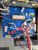
Ive pulled the secondary wires and measured from the center tap and got red & red 57vac each & brown 18vac each? The only thing I can see that is wrong? is the center tap,( red & yellow)wire goes to the positive on the main filter cap and on the schematic it goes to chassis? You can see in the photo that I had swapped the grey wire with the white wire on the primary side to see if it made a difference? (it didn't)This is where it has 6 connections black black,white white & red grey. It looks like the photos have disappeared? Thats weird they are back?
Attachments

Last edited:
OK, so the transformer is doing what it ought to, but your wires are wrong? Look at the schematic, center tap must be grounded. Not sure just what I am looking at, but isn't the white wire ground? There is not just A main filter cap, there are two, so the positive on one of them will be ground.
So something in the wires or elsewhere is dragging the transformer around, but fortunately the tranny itself looks to be OK.
So something in the wires or elsewhere is dragging the transformer around, but fortunately the tranny itself looks to be OK.
I know there are two filter caps I just forgot the s, A friend of mine picked this amp up at an auction and asked me to have a look at it to see if I could fix it? The wiring was like this when I got it, so its obviously not wired right.Switch 1 is the main switch, would switch 2 be the 240-220 volt switch?(The red & white wires go to it in the photo)Primary side has black as active 240vac,white as 240vac back to neutral and grey the primary center tap. Ive never seen another one of these to compare the wiring,the pads on the power board that I have here are different to the one in the schematic? Thats why I've included photos in case someone knows where they go? A dim bulb doesn't show it dragging any current?
Last edited:
With the secondaries disconnected, you seem to get correct voltages on the secondary, so I have no reason to think you have any issues with the primary side. Yes, S2 is the 220/240 selector switch. Transformer wires: Black is common, gray is 220, and white is 240.
Don't know which schematic you have to compare. What number is in the corner? I am using the CS800X. Yours I think is a slightly older version, but they are extremely close. My layout matches your pictured board. The file size here won't let me post the schematic file. COntact customerservice@peavey.com and ask for your drawings.
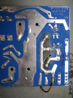
Just a thought. Your center tap should plug onto the little power board on the ground side - that wide copper trace across the center. But that in turn has to connect to the chassis. Check for continuity from that place on the board and the chassis to make sure that actually does go to ground. A missing ground there would allow the circuit to pull the windings off center.
Other ideas in my head might be to disconnect the power supply feeds to the two big circuit boards, then see if the power supplkies themselves are working unloaded.
Don't know which schematic you have to compare. What number is in the corner? I am using the CS800X. Yours I think is a slightly older version, but they are extremely close. My layout matches your pictured board. The file size here won't let me post the schematic file. COntact customerservice@peavey.com and ask for your drawings.
Just a thought. Your center tap should plug onto the little power board on the ground side - that wide copper trace across the center. But that in turn has to connect to the chassis. Check for continuity from that place on the board and the chassis to make sure that actually does go to ground. A missing ground there would allow the circuit to pull the windings off center.
Other ideas in my head might be to disconnect the power supply feeds to the two big circuit boards, then see if the power supplkies themselves are working unloaded.
I contacted Peavey usa with the serial# and they sent me the 1989 series schematic. I mentioned in my original post that the power supply is not connected to anything?Thats probably why there is no continuity to chassis on the power board? I just measured switch 2 and I think it may be the problem because its all over the place from 30vac to 250vac on both 220v and 240v? Im being super careful that I dont burn this amp out because its not mine,if it was mine it would be a different story LOL.
Last edited:
You can hard wire around that switch, but if your secondary voltages are right, then I tend to doubt that switch is a problem. I have to ask what you are measuring voltage with respect to on that switch?
OK, I assume you mean the connections to the channel boards? But all the wires trail off to somewhere, and one of those ought to be a chassis connection? My underlying concern is that whatever we are using as a reference point - usually the chassis - for ground might not be connected to the common of this supply?
I mentioned in my original post that the power supply is not connected to anything?Thats probably why there is no continuity to chassis on the power board?
OK, I assume you mean the connections to the channel boards? But all the wires trail off to somewhere, and one of those ought to be a chassis connection? My underlying concern is that whatever we are using as a reference point - usually the chassis - for ground might not be connected to the common of this supply?
You can hard wire around that switch, but if your secondary voltages are right, then I tend to doubt that switch is a problem. I have to ask what you are measuring voltage with respect to on that switch?
OK, I assume you mean the connections to the channel boards? But all the wires trail off to somewhere, and one of those ought to be a chassis connection? My underlying concern is that whatever we are using as a reference point - usually the chassis - for ground might not be connected to the common of this supply?
I cleaned the switch then connected the main board up and everything is working pos 76vDC neg 76vDC Pos15.5DC, Neg15.4DC and 24vDC. Except for 1 channel,all the output transistors are working.I think it maybe on 1 driver board I checked all the transistors were OK then recapped it and moved it to the other side and the problem went with it.One side has the green light when the relay clicks in, the problem side has no lights at all? The 15v regulator is OK,so it must be the op-amps do you think?
- Status
- This old topic is closed. If you want to reopen this topic, contact a moderator using the "Report Post" button.
- Home
- Amplifiers
- Power Supplies
- Peavey CS800, no Power