This might not be as easy as you think. I couldn't turn anything up on this but just thinking about it... I think that to fire at the peak of the voltage would require the circuit to 'have knowledge' of the frequency so that it can delay firing for 90 degrees from a known zero crossing. The voltage isn't a constant and so can not be used.
Zero crossing devices will work at any frequency and voltage because the zero cross point is an absolute. To do what you want would need a zero crossing detector firing a drive circuit after 5ms for UK mains. And to keep doing that. Not easy.
Or perhaps a circuit that waits a second or two after power on before enabling drive to the triac, and that circuit would also have a second zero cross input to start the initial sequence.
I can see the 5ms delay requirement for 50Hz mains supply.
Applying that after a zero crossing Triac should give a repeatable close approximation to a peak switching.
I suspect that the peak switching probably only needs a delay accuracy of +-10% on the 5ms to be close enough.
Would the delay only apply at first crossing and then no delay for all subsequent triggers while I require to triac to remain ON?
Yes, the first crossing is the critical one. After that the triac would be fired continuously which in a discrete circuit might be via a small pulse transformer fed from a high frequency source.
(I tried a little while ago to switch a large toroid this way in the hope of devising a slow start and the results weren't good. I absolutely annihilated a 6.3amp fuse, and when it did run the toroid was really growly)
(I tried a little while ago to switch a large toroid this way in the hope of devising a slow start and the results weren't good. I absolutely annihilated a 6.3amp fuse, and when it did run the toroid was really growly)
Attachments
Hi,
Starting anything at the absolute peak voltage will generally cause a lot of inrush current. The reason that zero crossing detectors exist is to connect the the mains with a minimal amount of fuss and bother from the load circuit.
If you want to generate lots of line noise, I guess this is one way to do it.
Andrew, if you don't mind me asking, what is it that you are wanting to do switching here?
-Chris
Kind of sounds like a circuit we needed to fire antiparallel SCR's into a highly inductive load. It was a high current test set capable of around 50 kA. We needed to remove any chance of DC offset, which is affected by the initial firing angle and X/R ratio of the load (which would change slightly from device to device).
The circuit would find the zero crossing and trigger a 555. Simple one-shot with adjustable time delay to effectively dial in the amount of needed delay. Typically about 70 degrees of delay was just right for a wide range of loads, but we had the ability to tweak as necessary. Once the circuit was fired, it was simply gated on continuously to maintain AC switch behavior.
What is your application?
I would like to try a soft start using a triac as the resistor bypassHi,
Starting anything at the absolute peak voltage will generally cause a lot of inrush current. The reason that zero crossing detectors exist is to connect the the mains with a minimal amount of fuss and bother from the load circuit.
If you want to generate lots of line noise, I guess this is one way to do it.
Andrew, if you don't mind me asking, what is it that you are wanting to do switching here?
-Chris
and if using one for that, then another triac to turn on the transformer from a cold start.
But a transformer starting at zero crossing is almost worst case for starting current.
Turning on at maximum voltage reduces the starting current significantly.
That may allow a much lower added resistance, or if it turns out to be very good, then no added resistance and saving the delay triac that bypasses the resistor.
You could use the CD4046 integrated circuit to phase lock onto the mains waveform. If you use phase comparator number I then the 4046 output will be phase shifted by 90 degrees -- exactly what you want! The rising and falling edges of the 4046 output are aligned with the peaks and troughs of the mains voltage.
The good news is, this a VERY low speed circuit (50 Hz!) and you can prototype it on your solderless breadboard very easily. Signal generator, or little NE555 oscillator, provides 50 Hz "mains waveform". Your CD4046 single chip PLL, with the external R's and C's you have selected, produces the 90.0 degree phase shifted output. Put input and output waveforms up on a dual trace oscilloscope and tweak your design until it's as perfect as you require.
You might want to gate this with a "power has been good for 600 milliseconds" startup delay signal, just to make sure you're not firing the triac until all other wakie-uppie support circuits have powered up and stabilized. I'd suggest putting that through a two or three stage synchronizer, before the enable gate that connects the 4046 to the triac driver, to ensure the enablement happens smoothly, far far away from the clock edge.
Last edited:
I would like to try a soft start using a triac as the resistor bypass
and if using one for that, then another triac to turn on the transformer from a cold start.
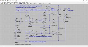
I have a circuit beyond a prototype stage (i.e. it works) that uses a triac + resistor to soft start a toroid and then a few moments later the triac is shunted by a solid state switch.
The logic circuit allows on/off via a simple logic input such as a uP or a PIC etc, or just a simple low voltage manual switch. For safety it should be power from a low voltage standby supply... other methods of obtaining a suitable low voltage low current supply are available of course, but are outside of the forum rules.
The triac fires first and turns off last. The FET switch places a low impedance shunt over the triac effectively killing any commutation noise etc. High voltage FETs are easily available, I used BUZ11's from my TV repair days. Not the most suitable choice in terms of current rating and low Rds but they worked perfectly. The tranny was a 650VA toroid.
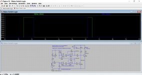
You can see the timing here. The circuit should run straight off in LTspice as it uses standard library parts. The delays are easily changed by altering the time constants.
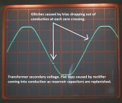
The triac drive used an MOC3023 ? (from memory) operating on a power triac like the BTA/BTB16-600B. You need a triac that will fire in all four quadrants. I didn't have such a device and you can see the glitches that that caused here. Of course once the FET shunts it the problem goes away but better to do it right from the start.
The FET switch is a copy of the well known speaker relay version that uses a photovoltaic coupler but with FET's suitable for mains use.
Attachments
Is there a way to achieve a peak crossing triac switch using either a zero crossing opto triac (moc3041), or a random opto triac (moc3021, or vom3052)?
Something very simple please.
I did a soft start project about a year ago.
I used a 8 pin PIC micro to ramp up the phase angle slowly.
It just needs a cheap PIC micro a opto isolator and a triac.
The PIC just needs a few mA to work so a simple mains power supply dropper with a diode and cap is all that is needed.
Depending on how much power is used will affect size of triac heat sink.
The mains reference is simply a 390K resistor into a PIC i/o pin.
An externally hosted image should be here but it was not working when we last tested it.
Last edited:
It occurs to me that Douglas Self's recommendation to use a relay and a resistor, might turn out to have very nice timing properties when you choose the right relay. I see that inexpensive relays with high current contacts like the RTD34012 are available with a datasheet guaranteed maximum pull-in time of 8 milliseconds.
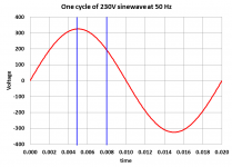
If the manufacturer has added standard amounts of guardband and safety margin and C.Y.A. so that essentially 99.999% of functioning relays meet this spec (there is no "yield loss" when otherwise good parts must be discarded because they don't meet this spec), then I expect that real relays measured in the real world will have a pull-in time somewhere betweed 5 milliseconds and 8 milliseconds. I've placed vertical blue lines at 5 msec and at 8 msec in the Figure below.
Cowabunga! This is near-as-dammit to switching at the mains peak! Switch the relay coil @ zero crossing, the contacts switch at the peak. If the timing is off a little bit either side of the peak, so what! That's what the resistor is for! It limits the inrush current. (In an inductor, AC voltage leads AC current by 90 degrees. "ELI the ICE man").
Recall that 230VRMS = 325V peak.
Attachments
Cowabunga! This is near-as-dammit to switching at the mains peak!
I can see where you're coming from on that. Its an interesting idea, and I've seen stranger.
Cowabunga ! (must remember to cross you off the Christmas card list
 )
)
A zero crossing triac to trigger a 555 that inserts a 4ms to 4.9ms delay to trigger the main switching Triac seems to be the simplest.
Any others?
What needs to be done to achieve the 4 quadrature switching?
Any others?
What needs to be done to achieve the 4 quadrature switching?
You need a triac that will fire in all four quadrants.
What needs to be done to achieve the 4 quadrature switching?
Choice of triac. The data sheet should show what it is rated for.
Andrew... I might have to revise my thinking on the triac choice (although ultimately it is application and driver specific)
Attachments
- Status
- This old topic is closed. If you want to reopen this topic, contact a moderator using the "Report Post" button.
- Home
- Amplifiers
- Power Supplies
- peak crossing Triac switch ?