Hi there guys. I am working on an ambitious project to design/build my own multi-channel car amp. I've got working SMPS boards and now am testing the PA100 LM3886-based boards!
They sound great but with no input signal, good +/- 25V, and 8 ohm load, they generate quite a bit of heat on the heat sink! (Hot to the touch)
I measured about .13 A on the +V line DC current, idle, and did not see big oscillations on the output jack. Also, DC offset on output seems to be tiny!
I was wondering if you might have any ideas of what is TYPICAL no-signal power dissipation for these, or possibly my error(s)?
My design is basically the National Semiconductor reference design, with 0.1% parts where recommended.
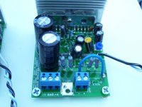
Attachments
The heatsink I'm using for test purposes is 3-13/16" x 1-9/16" x 3/4"H (not as shown).
Also, I guess "idle" power dissipation =
.13 A x (+25V - [-25V]) = .13 * 50 = 6.5W
....unless I'm incorrect
Thanks for your help I am just really concerned and frustrated...
Also, I guess "idle" power dissipation =
.13 A x (+25V - [-25V]) = .13 * 50 = 6.5W
....unless I'm incorrect
Thanks for your help I am just really concerned and frustrated...
Attachments
Heatsink too small / poor air flow?
I have 6 x LM3886's on a heatsink which is 200mm wide x 75mm high x 40mm depth (fins) and a 10mm thick base. It got just warm when testing outside of a case for an extended period of time at loud volume (many hours), but gets boiling hot just idling inside my temporary case, which happens to have zero ventilation, unfortunately.
I have 6 x LM3886's on a heatsink which is 200mm wide x 75mm high x 40mm depth (fins) and a 10mm thick base. It got just warm when testing outside of a case for an extended period of time at loud volume (many hours), but gets boiling hot just idling inside my temporary case, which happens to have zero ventilation, unfortunately.
Hi,
if you are sure it/they are not oscillating then your heatsink is simply too small.
A single central bolt is insufficient to clamp a pair of chipamps. Straddle each chipamp with clamping bolts. Have you used Thermal compound between the TF package and the sink?
The in car environment is severe. You will need very large heatsinks to prevent the protection circuits cutting in.
BTW,
that Cin=0.1uF will filter most of the bass from your input signal. (-1db @ 300Hz).
I would try a range of input caps between 1uF and 8uF to see which best suits your needs.
Thanks for the reply you caught that Cin value error I hadn't noticed! ARrrggh! I knew the right value and still used the wrong one somehow 
Well I have been trying with thermal grease and plan on using better clamping also. I will test with bigger heatsinks also.
But I will try the Rf (feedback resistor) bypass capacitor & resistor I saw mentioned by someone else. Otherwise I was not sure how to verify oscillation.
The idle power dissipation seems pretty large!
One way to find out is to consulting the datasheet. Have you done that?MartyM said:I was wondering if you might have any ideas of what is TYPICAL no-signal power dissipation for these, or possibly my error(s)?
It says 30-70 mA. Notice also that you wil get a current between the IC's via the outputs. Since you have the IC's in parallel, it's very important that you have exactly the same gain and also low offset.
Yes I have checked the data sheet(s) (of course). However as we engineers know, data sheets do not always reflect real world conditions, or what you'll get after production items are shipped.
Thus my question was in regard to idle heat and dissipation of those who have built the PA100 actually have experienced.
Yes as you can see in my schematic and etc. I have the same gain and offset. Thanks.
Thus my question was in regard to idle heat and dissipation of those who have built the PA100 actually have experienced.
Yes as you can see in my schematic and etc. I have the same gain and offset. Thanks.
heat
Simple, your heat sink is way to small, to check your offset you need to check each chip individually, separate and before you load sharing resistors, just because your getting an acceptable offset total does not mean your getting the correct picture overall, because a + offset on one chip can offset a negative offset on another and vise versa.
In a PA the chips are forced to there high - side dissipation under normal circumstances, so thats close to 80ma+80, simple use a bigger heat sink and your problem should be solved.
MartyM said:Yes I have checked the data sheet(s) (of course). However as we engineers know, data sheets do not always reflect real world conditions, or what you'll get after production items are shipped.
And as we engineers know, we need to use adequate heat sinks lest our projects go up in flames (which we call letting the smoke out).
Thermal resistance and temperature rise calculations are no more complicated than Ohm's law. Instead of voltage, the driving force is temperature difference. Instead of current we have heat, expressed in power dissipated (Watts). Instead of resistance, we use thermal resistance in degrees C/Watt. There has to be a circuit for the heat to flow, just like an electrical circuit. The circuit is defined where the two temperatures that make up the difference are measured- one is the die, the other is usually ambient air. The goal is to keep the temperature rise down to about 20-30C as this helps the semiconductors live a long, productive life.
You can measure the thermal resistance of your heatsink by mounting a resistor on it and applying DC power. Wait a while for the heatsink temp to stabilize. Calculate the power dissipated by the resistor (V*I), and then measure the temperatures of the heatsink and the ambient air. Divide the temperature difference by the power and your result is thermal resistance of the heatsink to ambient air in degrees C/W.
Your thermal circuit is just a series of thermal resistances in series. Total power is that dissipated by the amp chips (when they are driving a load). There is a die to package thermal resistance, a package to heatsink resistance, and a heatsink to ambient air thermal resistance. You can get numbers for the die to package and package to heatsink resistances from the data sheet. You have to measure or estimate the thermal resistance of your heatsink (or get it from the heatsink data sheet, if you have one).
Just as you can calculate the voltage across each of a string of series resistors, you can calculate the temperature rise across each thermal resistance and get a good estimate of the final die temperature above ambient. You also want to know the final heatsink temperature above ambient because if the heatsink is too hot, you might burn your fingers or other body parts on it. It's a good idea to keep heatsink temperature below about 45C for safety reasons, and even lower to keep the die temperature down.
Ultimately it is best to keep the die temperature as low as possible. That means using a large heatsink and/or a fan to force air across it. Of course, we all want our stuff to look nice and not be too big or cost too much, so we usually compromise and use a smaller heatsink and let it get kind of hot. At some point, adding a fan is cheaper and smaller than buying more heatsink, though we have to put up with the noise it makes.
Many people are under the mistaken impression that a heatsink sends heat off into never-never land. You'll see them putting heatsinks inside closed boxes. This will end in disaster eventually because the air in the box will heat up and the whole system will just keep heating up until the electronics die an uncomfortably warm death.
I_F
Hi and thanks for the replying regarding heatsink theory & application.
However I already knew all of that (these heat sinks were no more than test units....the "real world" I'll use will be based upon the thermal dissipation/theta parameters.
I just needed to make sure that others have had the same results-assuming no major errors, a few watts at idle are to be normally dissipated.
Thanks! I'll remove some shared resistors and check for any Vout differences.
I appreciate everyone's contribution!
- Status
- This old topic is closed. If you want to reopen this topic, contact a moderator using the "Report Post" button.
- Home
- Amplifiers
- Chip Amps
- PA100 Heat Issues...LM3886 Based..Any Ideas?