I've built some p3a board but some of them don't run correctly...
Without output transistor i've negative rail at the output...
ANy ideas?
If i connect positive and negative i've negative rail at output..
If i connect only positive i've a small positive at output...
If i connect only negative i've full negative at output...
Without output transistor i've negative rail at the output...
ANy ideas?
If i connect positive and negative i've negative rail at output..
If i connect only positive i've a small positive at output...
If i connect only negative i've full negative at output...
It seems that you could have a short somewhere or a transistor inserted the wrong way.... if you don't show us a pic I'm afraid we can't help much.
A pic of the board might do, even better to check the node voltages and send a pic of the schematic with the values written on the nodes.
Did you draw the boards yourself?
BTW it is better, to avoid damages, to provide supply voltages through a 100 Ohm 3-5W resistor per rail when testing amplifiers the first time.
Ciao
Andrea
An externally hosted image should be here but it was not working when we last tested it.
An externally hosted image should be here but it was not working when we last tested it.
An externally hosted image should be here but it was not working when we last tested it.
I hope that could help...
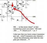
According to that schematic, you've got +30v AND -30V in the SAME PLACE on BC546. Two different voltages can't exist at the same time in the same place. I'm not great w/ terminology but it looks like thats the base of bc546 thats got both +30v and -30v at the same time...so which is it?
-Matthew K. Olson
-Matthew K. Olson
According to that schematic, you've got +30v AND -30V in the SAME PLACE on BC546. Two different voltages can't exist at the same time in the same place. I'm not great w/ terminology but it looks like thats the base of bc546 thats got both +30v and -30v at the same time...so which is it?
-Matthew K. Olson [/QUOTE]
NOOO!") One reffer to base and the other reffer emitter.
One reffer to base and the other reffer emitter.
-Matthew K. Olson [/QUOTE]
NOOO!
One reffer to base and the other reffer emitter.????????????did you also parallel 3 output transistors per
Everybody's right
The LED must be a problem because no voltage is dropped across it. Therefore the current sink for the long tailed pair is not passing any current.
From the photo of the board you can see 3 3-pin devices hanging off board. I and Mattyo5 presume that these are your output transistors. You need an emitter resistor for each one. The amp may also have trouble driving that many transistors. If you are using that many transistors because you are driving a heavy load then I'm afraid sooner or later your tracks on your board will burn as they are not chunky enough.
Where and how?You need an emitter resistor for each one
And i've already done one with five to drive a sub and run without any prob...
An externally hosted image should be here but it was not working when we last tested it.
An externally hosted image should be here but it was not working when we last tested it.
try this...this links to the original p3 article explaining how to parallel transistors...rod doesn't really recommend it, but i think it can be done..
http://www.sound.westhost.com/project03.htm
look at FIG 2
i'm w/ richieboy on this one
-Matthew K. Olson
http://www.sound.westhost.com/project03.htm
look at FIG 2
i'm w/ richieboy on this one
-Matthew K. Olson
You aren't going to be able to get a CFP output stage running stable with that many transistors hanging off of one driver transistor. Especially not on blob board like that. You need 0.1 ohm resistors in the emitter of each output transistor, or they won't current share and one set of transistors will be doing most of the work while the rest do little. This is where the CFP output stage is a big failing, more than one output transistor is a nightmare.
I must also say the overall construction of that board looks rather poor. It's not surprising you've got problems. If you've got full negative rail on the output, check the connections to Q6, the arrangement of the bootstrap R9, R10 and C5. Also check the current sink formed by Q3, R7 and R8 - if it's not working, the LTP won't function. The LED should be lit.
Why so many transistors ? You're not going to get 500W output from that circuit. You'd need higher rails of 80V or so, which is going to toast the BC546 transistors, and also require a total redesign. If this is the output power you want, choose an amplifier design that caters for it.
Have you checked the input ground connection that juices up your LED current source?
I have done many multiple BJT output device CFP's and CFT's and always use Re's (emitter) to the rail to ensure sharing, then you can bring them all back through the single reference one to output.
Cheers,
Greg
I have done many multiple BJT output device CFP's and CFT's and always use Re's (emitter) to the rail to ensure sharing, then you can bring them all back through the single reference one to output.
Cheers,
Greg
The P3A is a nice, simple, and effective design, but you need to redesign or make a different amp to start running huge power. There's simply not enough parts, and the BC546 transistors are not good for higher voltages. Also the P3A lacks resistors.
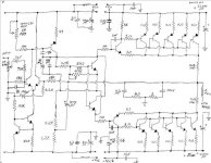
Here is a CFP amp with 5 pairs. You can look at this amp and get some ideas, and even you you have some ideas for me, I'm open to hear them. But I figured you can see how many extra parts I add to add to have 10 output transistors.
My amp uses 2SC2632 150V small signal for diff and current source, and used 350V MJE15034/35 for vas and drivers, and 350V MJL4281/4302 for outputs.
This is my own design, not a copy or clone of the P3A, but you may see some similarities. Don't be too confused by the dual VBE transistors, they are for sensing temp on 2 heatsinks. I used the Onsemi transistors because they are high quality transistors for cheap.
So far this amp has been tested and very stable up to +/- 52V but will be moving to +/-70V soon when I finish building. Goal is around 350-400W.
Thing I noticed a lot with CFP is you need some emitter resistors for the drivers and the bases, and it helps a lot with stability. Also, I'd recommend heatsinking your VAS and drivers, as my VAS gets warm with a heatsink, I'd hate to think how hot a naked transistor would be.
Also, your power transistors are halfway on the heatsink. The part hanging off gets hot too. I'd recommend getting the whole transistors on the heatsink, and putting them in the middle is even better than on the edge.
Attachments
- Status
- This old topic is closed. If you want to reopen this topic, contact a moderator using the "Report Post" button.
- Home
- Amplifiers
- Solid State
- p3a problem