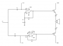
Hi! A while ago I made a small guitar amp with a power amplifier based on an op-amp driver and a darlington push-pull output stage, a simpler version of the circuit described here: Opamp Based Power Amp. It works great, but it's limited to about 8-10W output into a 8 Ohm load due to the maximum Vpeak of ~13.5V from the op-amp and I've been pondering a way to increase that without sacrificing the simplicity of the circuit. This made me think about bridging two op-amps into a BTL-type circuit as illustrated in my attached image. I realize that a working circuit would need additional components to be stable and that the resistors would have to be carefully chosen so that the gain of the two op-amps are identical, but the circuit illustrates the concept. The output transistors would typically be TIP122/127.
So to the question; is there something obviously stupid with this approach or do you think it could work? Just using an LM1875 or going with a more conventional lin topology amp is probably both easier and better sounding, but I'm a beginner and I love the opportunity to learn! 😀
So to the question; is there something obviously stupid with this approach or do you think it could work? Just using an LM1875 or going with a more conventional lin topology amp is probably both easier and better sounding, but I'm a beginner and I love the opportunity to learn! 😀
Attachments
Last edited:
Drawn as it is , q1 can only source current and q2 can only sink current.
Great for sure, but that's half of the job.
The coupling caps will charge to their max level, and the show will end there.
It is perfectly possible to use two full amps in BTL configuration, but that's well known and you can find 1,000 of examples on the net
Great for sure, but that's half of the job.
The coupling caps will charge to their max level, and the show will end there.
It is perfectly possible to use two full amps in BTL configuration, but that's well known and you can find 1,000 of examples on the net
So to the question; is there something obviously stupid with this approach or do you think it could work? Just using an LM1875 or going with a more conventional lin topology amp is probably both easier and better sounding, but I'm a beginner and I love the opportunity to learn! 😀
As a conceptual drawing it's not stupid ... but I doubt you would get it to work without a ton of extra parts.
I'm thinking you would do better to look into an output stage after the opamp with a bit of gain. With the right voltage dividers you could still control feedback from the opamp, easily enough.
The use of an non-inverting opamp and an inverting opamp to drive this outputstage yields in no output whatsoever. The nodes on the loudspeaker are (almost) exactly the same but opposite. So the netresult will be zilch.
Even more, this non-inv <> inv configuraton will create a very nasty pole in the lower mid band, which should be sucked out with a serious notch filter.
To prevent this, start with instrumentation opamp configurations, both driving full complementary biased outputstages (aka bridge mode) and compensate for surprising poles.
Thanks for the feedback, guys!
Douglas Blake: That's an interesting idea indeed! What you're suggesting is that I could get away with a single op-amp stage powered from a dual supply and simply insert a common class A VAS-stage (BD139, BC546 or similar) before the output transistors, right? That would leave me with an available op-amp for the preamp/tone control stage, which would be perfect!
Douglas Blake: That's an interesting idea indeed! What you're suggesting is that I could get away with a single op-amp stage powered from a dual supply and simply insert a common class A VAS-stage (BD139, BC546 or similar) before the output transistors, right? That would leave me with an available op-amp for the preamp/tone control stage, which would be perfect!
So here was my thinking; the input of the upper non-inverting op-amp is biased to +15V (with an op-amp supply of +30V) and the lower inverting op-amp is biased to -15V (with an op-amp supply of -30V) so that they both carry the whole cycle of the signal, but 180 degees out of phase. I was thinking that this would mean that the output of the upper op-amp would have a maximum swing from +1.5V to +28.5V and the lower from -1.5V to -28.5V. Connecting a load between these nodes (AC-coupled) should mean that the load sees a maximum voltage of 57V. Is this correct or am I way off?
For the actual output stage I'm more in doubt if my creative arrangement could ever work. After thinking about this some more I can definitely see that there would be a issue with crossover distortion, since the bases need to be at a 0.7V potential above/below the emitters to avoid it and as soon the the output capacitors in my circuit have initially charged up, the base and the emitter are at the same potential. The fact that the bases are at +/-15V with respect to ground at idle, doesn't help.
For the actual output stage I'm more in doubt if my creative arrangement could ever work. After thinking about this some more I can definitely see that there would be a issue with crossover distortion, since the bases need to be at a 0.7V potential above/below the emitters to avoid it and as soon the the output capacitors in my circuit have initially charged up, the base and the emitter are at the same potential. The fact that the bases are at +/-15V with respect to ground at idle, doesn't help.
Yes, way off....am I way off?
Beyond the horizon.
In a bridged configuration there are two complete amplifiers working in antiphase. You have a single, broken amplifier. There is no DC path through the output devices so no current can flow. Perhaps you were thinking two class A outputs each with a load resistor? The inefficiency of that is problematic, but you need to actually use a working class A output.
The shifting of DC voltage is to no result as you AC couple the load anyway.
You might want to contemplate the opamp tripler circuit from this posting: https://www.diyaudio.com/forums/sol...stacking-voltage-operation-4.html#post5954865
The shifting of DC voltage is to no result as you AC couple the load anyway.
You might want to contemplate the opamp tripler circuit from this posting: https://www.diyaudio.com/forums/sol...stacking-voltage-operation-4.html#post5954865
Last edited:
Out of courtesy won´t use the word "stupid" but that circuit is definitely a mess and will never ever work.the circuit illustrates the concept. The output transistors would typically be TIP122/127.
So to the question; is there something obviously stupid with this approach or do you think it could work?
Use a normal, time tested circuit.Just using an LM1875 or going with a more conventional lin topology amp is probably both easier and better sounding,
Throwing random parts on the table and soldering them together is not "learning" by any means.
FIRST learn, THEN design and build.
Plan B:build a time tested circuit and later leqrn the proper way.
We all were beginners, some took the longer but proper way to go on.but I'm a beginner and I love the opportunity to learn! 😀
Thanks for the feedback, guys!
Douglas Blake: That's an interesting idea indeed! What you're suggesting is that I could get away with a single op-amp stage powered from a dual supply and simply insert a common class A VAS-stage (BD139, BC546 or similar) before the output transistors, right? That would leave me with an available op-amp for the preamp/tone control stage, which would be perfect!
Yep... you could easily have the opamp on the traditional +-15 supplies then couple it's output into a X2 or X3 amplifier stage tied to your bulk rails. From there you're designing a traditional class AB output stage. The big difference is that your speaker to input feedback goes through a voltage divider back to the opamp's negative input.
But that's nothing new... several other successful amps have used this topology.
Out of courtesy won´t use the word "stupid" but that circuit is definitely a mess and will never ever work.
We all were beginners, some took the longer but proper way to go on.
How many of your early designs failed in a nice puff of stinky smoke?
I think we've all had a few of those.
None.
First learn. To calculate. Learn designing. Calculate. Know the formulae. Read. Read. Read. Calculate. Absorb everything involved. Calculate. Learn. Solder one bjt to a resistor. Nothing happens other then expected. It was calculated. No puff. No smoke.
None.
(Now I'm courtious.)
Read my signature below. Understand them.
Last edited:
Yep... you could easily have the opamp on the traditional +-15 supplies then couple it's output into a X2 or X3 amplifier stage tied to your bulk rails. From there you're designing a traditional class AB output stage. The big difference is that your speaker to input feedback goes through a voltage divider back to the opamp's negative input.
But that's nothing new... several other successful amps have used this topology.
Right, thanks! I'm not trying to reinvent the wheel here, so the fact that this is a well tested topology is just fine. My main goal is to design a simple, meaning low parts count and easily understandable, guitar amp based on more-or-less discrete components (no vendor specific chips) running from an unregulated +/-22V dual supply. I've loooked into the DIGI-125, but frankly I find the long tailed pair somewhat confusing and much prefer the user friendliness of an op-amp. Your suggestion sounds perfect for his!
As for my attempted circuit, my idea was to try to get away with a single pair of output transistors (instead of two pairs) while still running in BTL-mode to get the benefit of the increased voltage swing. Judging from the comments in this thread, though, it seems my attempt was rather poor...
")
Your suggestion sounds perfect for his!
If you're only shooting for 22v there are opamps that can work directly from those voltages which will simplify your design even further. For example the OPA454.
But, if you are only shooting for 22v why not go with one of the many chip amps or even go with a class D module. There are tons of them to choose from...
my idea was to try to get away with a single pair of output transistors (instead of two pairs) while still running in BTL-mode
Bridge-tied means there are two amplifiers. So you double up the components. There's no cheating this. If you start with an amp with a single output transistor (class A with passive load), then you can double this up to two transistors, but that's a very different amp configuration.
- Status
- This old topic is closed. If you want to reopen this topic, contact a moderator using the "Report Post" button.
- Home
- Amplifiers
- Solid State
- Op-amps in BTL configuration - fundamentally flawed or possible?