Hi folks . . .
I'm trying to design a crossover for an MTM system using a pair of SEAS ER18RNX wooofers and a 27TDFNC/GW tweeter. Zaph Audio has a 2-way system, the SR71, using the same woofer, but a different SEAS tweeter. Specs for his drivers are:
Tweeter: 6 ohm (nominal) Re = 4.8 ohm
Woofer: 8 ohm (nominal) Re = 5.9 ohm
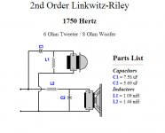
Crossover 1750Hz.
Actual component values Zaph uses:
Hi-pass filter: C1 = 12uF
L1 = 0.15mH
Lo-pass filter: C2 = 12uF
L2 = 3.3mH
Both filters are LR2.
But two different calculators give these values:
--- if you use nominal impedance:
C1 = 7.58 uF
L1 = 1.09mH
C2 = 5.69uF
L2 = 1.46mH
--- if you use Re:
C1 = 9.48
L1 = 0.87mH
C2 = 7.71uF
L2 = 1.07mH
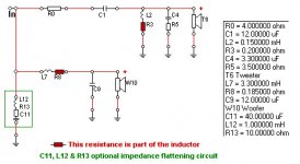
2-Way Crossover Designer / Calculator
mh-audio.nl - Crossover Networks
The audio.nl calculator indicates you should use Re. The DIY merely asks for "speaker impedance," which one would assume to be the nominal impedance.
Which should one use?
In either case the values are wildly different from those Zaph is using. He does have a notch filter on the tweeter. Does that resistance need to be included in the tweeter Re? Does it affect the values of the woofer cap and coil also?
I've done these comparisons with a couple other actual v. calculated crossovers. None of them agree.
Are these calculators of any value? Am I misusing them?
Thanks for any help!
I'm trying to design a crossover for an MTM system using a pair of SEAS ER18RNX wooofers and a 27TDFNC/GW tweeter. Zaph Audio has a 2-way system, the SR71, using the same woofer, but a different SEAS tweeter. Specs for his drivers are:
Tweeter: 6 ohm (nominal) Re = 4.8 ohm
Woofer: 8 ohm (nominal) Re = 5.9 ohm
Crossover 1750Hz.
Actual component values Zaph uses:
Hi-pass filter: C1 = 12uF
L1 = 0.15mH
Lo-pass filter: C2 = 12uF
L2 = 3.3mH
Both filters are LR2.
But two different calculators give these values:
--- if you use nominal impedance:
C1 = 7.58 uF
L1 = 1.09mH
C2 = 5.69uF
L2 = 1.46mH
--- if you use Re:
C1 = 9.48
L1 = 0.87mH
C2 = 7.71uF
L2 = 1.07mH
2-Way Crossover Designer / Calculator
mh-audio.nl - Crossover Networks
The audio.nl calculator indicates you should use Re. The DIY merely asks for "speaker impedance," which one would assume to be the nominal impedance.
Which should one use?
In either case the values are wildly different from those Zaph is using. He does have a notch filter on the tweeter. Does that resistance need to be included in the tweeter Re? Does it affect the values of the woofer cap and coil also?
I've done these comparisons with a couple other actual v. calculated crossovers. None of them agree.
Are these calculators of any value? Am I misusing them?
Thanks for any help!
Attachments
The calculator only take into account limited data (e.g. impedance), and is just an approximation. Good speaker design take into account a lot more data, like the real frequency response of the drivers.
The calculator calculates a "gross crossover". Unusable for probably 99% of situations.
The calculator calculates a "gross crossover". Unusable for probably 99% of situations.
Gary, as newbie you should look into loudspeaker crossover design and Spice software for approximation to the final simulated projects.
Those calculators you show are only for a limited set of inputs like approx. calculation at one and only frequency, like using Re. Data sets from drivers (go look at spec sheets for your drivers) are in the time domain like impedance from 20Hz to 20KHz, so it's a curve. When calculating the crossover with a Spice type software you use variables (in the time/frequency domain or continuous/curves datasets) like impedance, output, phase in relation to each other. Those are many times called the frd/zma variables or data, that were measured and transfered to numbers to be used by the applications.
Vented-Box Loudspeaker CAD With SPICE
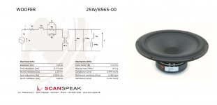
A Spice application works very much with those sets of data like the electric simulations of the ideal drivers as you can see in this simulation in the pic by Scan-Speak for driver 25W/8565-00 here. Notice Re that you mentioned, a T/S parameter, on the left of the picture.")
Those calculators you show are only for a limited set of inputs like approx. calculation at one and only frequency, like using Re. Data sets from drivers (go look at spec sheets for your drivers) are in the time domain like impedance from 20Hz to 20KHz, so it's a curve. When calculating the crossover with a Spice type software you use variables (in the time/frequency domain or continuous/curves datasets) like impedance, output, phase in relation to each other. Those are many times called the frd/zma variables or data, that were measured and transfered to numbers to be used by the applications.
Vented-Box Loudspeaker CAD With SPICE
A Spice application works very much with those sets of data like the electric simulations of the ideal drivers as you can see in this simulation in the pic by Scan-Speak for driver 25W/8565-00 here. Notice Re that you mentioned, a T/S parameter, on the left of the picture.
Attachments
I use the free version of SIMetrix SIMPLIS. It's much easier than LTSpice and, IMO, just as good.Really don't want to spend a year learning how to use SPICE.
There really isn't a way to cheat the design process. Sure it's just a circuit, but it reacts specifically to the individual driver on a unique baffle. The simulated process using Jeff Bagby's software is as good as you can get without measuring.
https://sites.google.com/site/undefinition/simulated-measurements
https://sites.google.com/site/undefinition/simulated-measurements
speaker workshop runs fine on my win7 64 bit.... I might have had to tell it to run in XP compatibility mode, can't remember...
the online calculators if you give them the actual impedance at the crossover point are good for getting a starting point, but that is about it.
Proper measurements (impedance and spl) and simulation with Jeff Bagby's PCD and Spekaer workshop should get you MUCH better results than what you could possibly get using online calculators. using SPL trace from manufacturers curves + above mentioned software should also give you much better results than the online calculators.
The simulators take into account the changing impedance of the driver AND the changing spl. The calculators assume these are both constant.
Tony.
for the same driver i will take Zaph Value or
we can try to make them with cheapest part
after that just keep them for another experiment
Yes, I'd trust Zaph's values also. But I need a method for calculating values for a design he doesn't have. Just used his designs to assess the accuracy of the online calculators.
The only way to know is to experiment. Sometimes "ideal" x-overs sound like crap. It is a pain, but the only way to please your particular ears is to relentlessly pursue what satisfies you. You need to take your listening environment into account. Basically, it is subjective. I have done the science for twenty years or more, and what sounds good, images, and creates a soundstage will ultimately be up to your particular ears. My system satisfies my every sonic desire, many agree, but my father believes it is missing something despite objective spectrum analyzation. So, to each his own. I tear mine down and add or delete passive components almost every two weeks, so there you go, if you like it then who cares? The solution, really, is to have your passive x-over located on the OUTSIDE of your cabinet, that way you can tweak away at will, and once you find audio Nirvana, hot glue it into your cabinet. Cheers, and good luck. (Madisound will give you the LEAP values for around 30 bucks, but I bet you still end up tweaking values of your components to suit your ears and your environment).
Last edited:
You are in luck, MS sells both of the drivers - it's worth the $30 to get your project started. Agree with assembling xo boards outside the cabinet - two smaller ones work out well also (each); don't cut all the leads on the parts, may be taking them back apart after a few days.
The only way to know is to experiment. Sometimes "ideal" x-overs sound like crap. It is a pain, but the only way to please your particular ears is to relentlessly pursue what satisfies you. You need to take your listening environment into account. Basically, it is subjective. I have done the science for twenty years or more, and what sounds good, images, and creates a soundstage will ultimately be up to your particular ears. My system satisfies my every sonic desire, many agree, but my father believes it is missing something despite objective spectrum analyzation. So, to each his own. I tear mine down and add or delete passive components almost every two weeks, so there you go, if you like it then who cares? The solution, really, is to have your passive x-over located on the OUTSIDE of your cabinet, that way you can tweak away at will, and once you find audio Nirvana, hot glue it into your cabinet. Cheers, and good luck. (Madisound will give you the LEAP values for around 30 bucks, but I bet you still end up tweaking values of your components to suit your ears and your environment).
The only way to know is to experiment . . . . The solution, really, is to have your passive x-over located on the OUTSIDE of your cabinet, that way you can tweak away at will, and once you find audio Nirvana, hot glue it into your cabinet.
I assumed that is what I'd end up doing. I designed the enclosure with separate compartments for the xovers, with removable backs.
(Madisound will give you the LEAP values for around 30 bucks, but I bet you still end up tweaking values of your components to suit your ears and your environment).
Yes. I ordered that service, and received a reply that it would take 4-6 weeks to produce the design. They asked if that was acceptable. I cancelled.
Gary, get hold of the impedance plots for the drivers, & read my sig...
(i.e. don't use nominal impedance or Re)
Ok. I have those plots. Will do. Thx!
Yes, I'd trust Zaph's values also. But I need a method for calculating values for a design he doesn't have. Just used his designs to assess the accuracy of the online calculators.
Maybe you can use this
http://www.diyaudio.com/forums/mult...designing-crossovers-without-measurement.html
Even if you use the specific impedance value at the crossover point, a crossover isnt a brick wall... Impedance will rise with frequency. At the minimum you should have someone figure out a zobel circuit to achieve a completely flat impedance curve, which will get you closer to usable results. I can easily do this for you if the drivers you're using have a manufacturers curve available.
You still will have no way of adjusting the response based on the acoustic offsets, for proper phase integration, but you can at least have a speaker without large peaks and dips.
You still will have no way of adjusting the response based on the acoustic offsets, for proper phase integration, but you can at least have a speaker without large peaks and dips.
FWIW Mark K's xover using this driver is better than Zaph's (& IIRC Zaph has said so):
The Seas ER18DXT ported two way
in particular, the notch filter makes a big improvement.
I have put together a no BSC version using the SEAS metal dome tweeter 27TBFC/G which works pretty well
The Seas ER18DXT ported two way
in particular, the notch filter makes a big improvement.
I have put together a no BSC version using the SEAS metal dome tweeter 27TBFC/G which works pretty well
- Status
- This old topic is closed. If you want to reopen this topic, contact a moderator using the "Report Post" button.
- Home
- Loudspeakers
- Multi-Way
- Online crossover calculators --- worth anything?